P0122 TPS GM 4.3 / [FIXED!!]
- Posts: 4441
- Thank you received: 966
Sorry about that!
"Ground cannot be checked with a 10mm socket"
Please Log in or Create an account to join the conversation.
- ScannerDanner
-

- Offline
- Administrator
-

- Religion says do, Jesus says done!
- Posts: 938
- Thank you received: 486
Don't be a parts changer!
Please Log in or Create an account to join the conversation.
Westfalia wrote: Tyler,
Yeah it is. None of that old thread we were working on could be migrated I was told. I forgot to mention it was the same problem child.
I had a bit of help from a shop and they told me "oh, it's the spider that's shorting things" and once the multi pin plug was disconnected from the injector (this has Central multi point) the short goes away. (BTW I could swear I did disconnect the EFI plug when I was trying to diag. the short, but I could have not had the key on or some other bonehead move as I was chasing my tail seeing as I really new at all this.)
Great I said. I Got a new spider(it was needing to be replaced anyway) and when I put the new one in and buttoned it up, the short was gone. I figured all is good. Turn the key on and the pump springs to life and we have DLC com, and it appears that the ECM-1 circuit is perfectly fine. Crank and it starts, but now I get the P0122 code and an EGR pintle code and a slightly rough rev. I pulled the EGR and checked it over put it back in and that code went away. We pick up the story over here on the new site.
So when I clip that wire(5V ref. GRAY) what am I looking for and where do I measure it at? I don't own a scanner btw. I guess before I do that, I'll put a tracer on that wire and hunt for a short.
The connectors look brand new with absolutely no corrosion. I'm in Southern CA and I think it rained about 9 months ago...maybeCorrosion is not one of our bigger problems. Heat is though.
I really am sorry we lost your old thread in the process
 Didn't mean to pull the rug out from under everyone, but I think it'll end up for the best. SO many issues we couldn't get around with the previous platform.
Super glad to hear that the short got resolved! Don't feel bad about the spider connection thing, it's very easy to do stuff like that on a complex diagnosis.
Please Log in or Create an account to join the conversation.
Tyler wrote: I really am sorry we lost your old thread in the process
Super glad to hear that the short got resolved! Don't feel bad about the spider connection thing, it's very easy to do stuff like that on a complex diagnosis.
No problem. Paul's stuff and your help are the only reason I'm this close.
So a bit of good news. As you suspected, it is a short on one of the ref. lines. After cutting one (pin 12 wire) ref. wire nothing happened, but when I cut the other(pin 21) wire, bam...5.1v!! Woo. Computer is good to go I guess. Now to find the short. So the things on that wire are the MAP, EGR, and something Mitchell calls the FUEL SENDER GAUGE MODULE(what ever the hell that is).
For the life of me I can not find the darn thing. Mitchell says it is on the left part of the dash but I can find no sign of it, unless it is buried up behind the metal super structure of the dash( no getting to that unless the entire dash comes out(not happening). We traced the faulted gray reference wire from the splice S118 (shown on Mitchell1 diagram pg. 3) over towards where it is supposed to connect up with the aforementioned FSGM. We came to a 4 wire plug( not the 5 wires shown on Mitchell) and unplugged there. 5v came back. Does that mean the short is between that point and the FSGM or could it be anywhere on the circuit??
The other parts of this circuit go to the MAP and the EGR. The gray wire also splits off from S118 and heads down the loom towards the trans and other things under the van. I've checked and nothing is obviously abraded or worn through, but no sign of a 6 wire module down there. I even checked the fuel pump plug seeing as the tank level/gauge sender is part of the fuel pump. No luck.
I'm going to ask over on the Astro/Safari forum and see if anyone knows where or what the FSGM is. As always, thanks!
Steve
Please Log in or Create an account to join the conversation.
- Posts: 4441
- Thank you received: 966
Attachment not found
Looks like it lives behind the DLC somewhere
Attachment not found
Nice work, looks like you have some good direction now! Watch the 5v line on the grey wire and see if it comes to life when you unplug it. Of course check the connector for damage or corrosion while you're in there.
We came to a 4 wire plug( not the 5 wires shown on Mitchell) and unplugged there. 5v came back. Does that mean the short is between that point and the FSGM or could it be anywhere on the circuit??
Was it just a connector in the middle of the harness somewhere, or a box/module/component?
The short would have to be from that point forward---toward the FSGM, if not the FSGM itself.
"Ground cannot be checked with a 10mm socket"
Please Log in or Create an account to join the conversation.

Westfalia wrote: The connectors look brand new with absolutely no corrosion. I'm in Southern CA and I think it rained about 9 months ago...maybe
I'm just crossing the border if you want to drive here I'll be glad to help you.
")
Please Log in or Create an account to join the conversation.
Westfalia wrote:
Tyler wrote: I really am sorry we lost your old thread in the process
Super glad to hear that the short got resolved! Don't feel bad about the spider connection thing, it's very easy to do stuff like that on a complex diagnosis.
No problem. Paul's stuff and your help are the only reason I'm this close.
So a bit of good news. As you suspected, it is a short on one of the ref. lines. After cutting one (pin 12 wire) ref. wire nothing happened, but when I cut the other(pin 21) wire, bam...5.1v!! Woo. Computer is good to go I guess. Now to find the short. So the things on that wire are the MAP, EGR, and something Mitchell calls the FUEL SENDER GAUGE MODULE(what ever the hell that is).
For the life of me I can not find the darn thing. Mitchell says it is on the left part of the dash but I can find no sign of it, unless it is buried up behind the metal super structure of the dash( no getting to that unless the entire dash comes out(not happening). We traced the faulted gray reference wire from the splice S118 (shown on Mitchell1 diagram pg. 3) over towards where it is supposed to connect up with the aforementioned FSGM. We came to a 4 wire plug( not the 5 wires shown on Mitchell) and unplugged there. 5v came back. Does that mean the short is between that point and the FSGM or could it be anywhere on the circuit??
The other parts of this circuit go to the MAP and the EGR. The gray wire also splits off from S118 and heads down the loom towards the trans and other things under the van. I've checked and nothing is obviously abraded or worn through, but no sign of a 6 wire module down there. I even checked the fuel pump plug seeing as the tank level/gauge sender is part of the fuel pump. No luck.
I'm going to ask over on the Astro/Safari forum and see if anyone knows where or what the FSGM is. As always, thanks!
Steve
Wow, so it WAS shorted. And here I was banking on high resistance, oh well. I still don't understand how this thing runs with the 5V ref shorted, maybe there's multiple regulators at work? Whatever, you're making progress!
Anyway, I decided to dig around in the wiring diagrams some more, try to ID this connector you disconnected to get 5V back. I *think* I found it, but beware, this diagram shows the 5V ref coming from a different pin on the VCM.
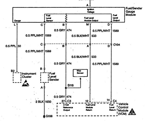
If the diagram is right, then your short is either in the FSGM itself, or on the gray wire between C104 and the FSGM. Side note, I like the OE diagrams because they include connectors (like C104) that Mitchell might leave out. But, OE diagrams usually don't give component locations, either

Please Log in or Create an account to join the conversation.
Noah wrote:
Attachment not found
Looks like it lives behind the DLC somewhere
Attachment not found
Nice work, looks like you have some good direction now! Watch the 5v line on the grey wire and see if it comes to life when you unplug it. Of course check the connector for damage or corrosion while you're in there.
We came to a 4 wire plug( not the 5 wires shown on Mitchell) and unplugged there. 5v came back. Does that mean the short is between that point and the FSGM or could it be anywhere on the circuit??
Was it just a connector in the middle of the harness somewhere, or a box/module/component?
The short would have to be from that point forward---toward the FSGM, if not the FSGM itself.
YOU ARE THE MAN! Where is that diagram from?? I have a complete set of GM factory books (for a '98 though) and they make no mention of it. Maybe they dropped it in '98 ??? I looked at that silly thing, and told my neighbor that it was the daytime running light box. :bangshead:
Yes, it was just a connector coming out of the harness. Lived behind the battery and went into the firewall and disappeared into a huge wire bundle and I guess out to that module. I traced all the wires from that S118 splice and marked them with colored tape on each end. That left the one gray that went over towards the firewall passthrough where there was a straight through connector but it only had 4 wires. Seeing the diagram you posted it makes sense now. The purple wire (the 5th one at the module) just goes FROM the module up to the gauge on the dash. That just never occurred to me when I look at that mitchell1 diagram. They need arrows on those damn things to indicate send/receive. LOL.
OK, so one more question. Why is it putting out a TPS code (p0122) for a gauge sender issue??
Please Log in or Create an account to join the conversation.
- Posts: 4441
- Thank you received: 966
Right Tyler? This this is die hard! Shorted 5v ref? Pshhh! 'Tis but a flesh wound!Wow, so it WAS shorted. And here I was banking on high resistance, oh well. I still don't understand how this thing runs with the 5V ref shorted, maybe there's multiple regulators at work? Whatever, you're making progress!
Good tip GeorG! I like your thought process.Unplug your computer and put a test light connected to battery positive, and see if it lights when you touch the TPS 5 volt wire wile you monitor that same wire with a multimeter (to avoid a feedback variable).
They need arrows on those damn things to indicate send/receive. LOL.
OK, so one more question. Why is it putting out a TPS code (p0122) for a gauge sender issue??
It's easy to get turned around reading those things. I do agree with tyler about factory diagrams. Not just for connector numbers, but also because sometimes the "simplified" diagrams can include TOO much stuff to look at, where as the OEM only gives you whats involved in running that particular component or circuit. (Sometimes that is).
As for the TPS code, I can only guess. Maybe that's just the most major player on that leg of the circuit and therefor has code set priority?
Don't quote me on that, just thinking out loud...
"Ground cannot be checked with a 10mm socket"
Please Log in or Create an account to join the conversation.
Noah wrote:
Right Tyler? This this is die hard! Shorted 5v ref? Pshhh! 'Tis but a flesh wound!Wow, so it WAS shorted. And here I was banking on high resistance, oh well. I still don't understand how this thing runs with the 5V ref shorted, maybe there's multiple regulators at work? Whatever, you're making progress!
Good tip GeorG! I like your thought process.Unplug your computer and put a test light connected to battery positive, and see if it lights when you touch the TPS 5 volt wire wile you monitor that same wire with a multimeter (to avoid a feedback variable).
They need arrows on those damn things to indicate send/receive. LOL.
It's easy to get turned around reading those things. I do agree with tyler about factory diagrams. Not just for connector numbers, but also because sometimes the "simplified" diagrams can include TOO much stuff to look at, where as the OEM only gives you whats involved in running that particular component or circuit. (Sometimes that is).
As for the TPS code, I can only guess. Maybe that's just the most major player on that leg of the circuit and therefor has code set priority?
Don't quote me on that, just thinking out loud...
OK, so one more question. Why is it putting out a TPS code (p0122) for a gauge sender issue??
RE: the P0122, I think you're right. Highest priority. Oh, and Tyler I just noticed I said pin "21" in that post. I meant to write pin "27". Same as the one in the factory diagram you posted. Same line. Pin 12 and 27 are the 5v ref. lines. Pin 4 is 5v RETURN.
Please Log in or Create an account to join the conversation.
Westfalia, you'll have to remind me, is there some history with this van? Just trying to connect the simultaneous shorted CPI assembly AND the shorted 5V reference.
Please Log in or Create an account to join the conversation.
GeorG wrote: Unplug your computer and put a test light connected to battery positive, and see if it lights when you touch the TPS 5 volt wire wile you monitor that same wire with a multimeter (to avoid a feedback variable).
Westfalia wrote: The connectors look brand new with absolutely no corrosion. I'm in Southern CA and I think it rained about 9 months ago...maybe
I'm just crossing the border if you want to drive here I'll be glad to help you.
Haha. If would drive I'd take you up on it. What border? TJ/San Ysidro?
Please Log in or Create an account to join the conversation.
Tyler wrote: Yeah, it may be that the TPS happens to have the most sensitive code set criteria. It may also be that setting a TPS code will prevent other codes from setting. Logic like that is often written in to cut down on setting false codes. As in, if there's an O2 circuit code present, the engine computer won't run the catalyst efficiency test until the O2 gets fixed.
Westfalia, you'll have to remind me, is there some history with this van? Just trying to connect the simultaneous shorted CPI assembly AND the shorted 5V reference.
I knew it was too good to be true. The black cloud is now back...again. I'll get to that in a moment.The history is that I've owned this thing since new in 1997 and with 350k I guess she's just ready to go to pasture. Lol.
History: I was having a fueling problem that killed a cat. I assumed it was a leaking fuel pressure regulator. I also got word from my oil analysis that there was coolant in the oil again(these motors have issues with the lower IM gaskets going bat at the front right water port). So knowing that, I dug in again and pulled the upper/lower intakes replaced the gasket and being a cheap ass bastard I did not put a new spider in and only replaced the regulator. Buttoned it all up and put it back on the road. It ran perfect for 2 weeks. One afternoon coming around a corner it just shut off. Dead short on that ECM-1 line that started that old thread. Why did that happen? I really have no idea. We only discovered the 5v reference issue after I put in the new spider. Once I did that the ECM-1 issue went away.
Cut to this thread and yesterday's adventures:
Per your help/suggestions I was able to get 5v back and was tracing it down to that sender gauge module. Thanks to you I found it, and with everything showing that the ref. wire short (.14-.15 v) was narrowed down to that module, I went to unplug it to confirm. The module is a circuit board that slides into a hard wired box/connector. You can't for some reason just unplug it. So, I opened the cover on the plastic box and carefully slid the board out from it’s wire contacts and examined it. Nothing burned and it looked in perfect condition. I asked my helper to confirm that the reference line jumped back up to 5v. I was shocked and dumbfounded when he said it read 0v! "Huh?" 0v he yelled back. " M F*#!er, you got to be kidding me??!!" I went to check and sure enough .002v. OK, let’s see, and sure enough NO power to the computer at the B+ orange wire (pin 4 I think). Go to the ECM- B fuse at the under hood convenience center and I’ll be dammed, the fuse is burnt!
I check with a test light and yep, dead short. DIFFERENT from the previous one which was on the ECM-1 circuit. This is the ECM-B circuit. I check and unplug all of the components on it(oil pressure switch, fuel pump relay, VCM). Pulling the oil pressure switch and FP relay do nothing, but pulling a plug on the computer removes the short. I checked the fuel pump at the test lead, and it shows short to ground there too.
I looked to see where the ECM-B is getting its power from and obviously it’s coming from the ignition. Removing the white or black multi pin connectors from the computer removes the short. I removed the big pass through multi pin connector at the firewall, and the short went away. Am I doing this wrong or are these just signs that the short just has not been found and the results are showing up in other areas?
Good thing I don’t do this for a living…I’d of been fired weeks ago. LOL. I think my wife is about to fire me anyway. She says give up and buy something newer. Ha.
steve
Please Log in or Create an account to join the conversation.
- Posts: 4441
- Thank you received: 966
Back to the diagrams! lol
"Ground cannot be checked with a 10mm socket"
Please Log in or Create an account to join the conversation.
Posting the diagram for reference:

So just to be clear, if you replace the ECM-B fuse, it pops immediately? I know that the test light is showing a short, but that may be because the test light is finding a ground through the VCM as it normally should.
I've seen shorted GM modules before, but usually they're BCM's that use higher load circuits. If you find that the ECM-B fuse pops immediately, then you could always try your other VCM. I know, it gives you a start/stall, but it'd at least prove out the failed VCM.
EDIT: Image uploading isn't working, I'll try later.
Please Log in or Create an account to join the conversation.
Tyler wrote: Ah don't sweat it, man! Multiple failures is just part of the game. Any shop you'd take this to would be dealing with the same problems. Heck, they might not have even gotten this far yet.
Posting the diagram for reference:
So just to be clear, if you replace the ECM-B fuse, it pops immediately? I know that the test light is showing a short, but that may be because the test light is finding a ground through the VCM as it normally should.
I've seen shorted GM modules before, but usually they're BCM's that use higher load circuits. If you find that the ECM-B fuse pops immediately, then you could always try your other VCM. I know, it gives you a start/stall, but it'd at least prove out the failed VCM.
EDIT: Image uploading isn't working, I'll try later.
You know, my helper was saying put a fuse in and see if it blows, but I said "why? It's showing a short with the test light...see". I should listen to him more...ha.
So if I put the fuse in and it blows right away, then the computer is bad? I'll check with a fuse and the other computer though. Oh, not sure I mentioned it. The test lead to the fuel pump was shorted to ground too. Would an internal short in the computer do that? Guess I need to test the fuel pump relay too since it's on that circuit. I'll unplug the pump from the harness and try and power it with my power probe to confirm it still works.
What would make that ECM-B circuit fail just by unplugging a fuel sender module? Odd. Oh, can I send 12v to the computer to try and power it up independently, or will this fry it since it seems to be grounding out?
Just to be clear, could all of these multiple issues have one root cause? Or are they just issues I'm causing messing around with things? I know there is no answer without seeing it in person, but can a ground issue in lets say the fuel pump or the fuel level sender feed back through a circuit and cause issues within the computer? Grasping at straws now. Haha.
The original failure was so sudden and complete, you'd think it would only be one thing, and not cascading multiple faults. Is there a diagnostic I can run on the computer to test it?
Look what I just ran across....hmmm. . :blink: Bad PCM causing false TPS code troubleshootmyvehicle.com/gm/4.3L-5.0L-5...m-causing-tps-code-1 This is for a few years prior to my '97, and the pin positions are different, but otherwise its the same. One interesting note is he says to unplug the Coolant Temp Sensor as it's in this circuit somehow. Not done that yet. I'll re read.
<edit> Just found the '97 pin outs from the same site. troubleshootmyvehicle.com/gm/4.3L-5.0L-5...uts-1996-1997-page-3
Thanks a s usual guys!
Please Log in or Create an account to join the conversation.
I guess I should caution you (and others) about test light short finding. If there are any loads that are permanently grounded (like fuel pumps and VCM's) on the circuit you're testing, then the test light will light. This is why the test light shows a short when connected to the fuel pump test connector: It's finding a ground through the pump itself. Just FYI.
As for what caused the ECM-B fuse to pop, not sure? I'm inclined to revisit that later if the fuse pops again. It may be that there's more going on in this harness than we know about. I don't see a fuel pump ground or level sender causing fuses to pop like this, but please don't feel bad about trying to connect the dots! Sometimes we can connect multiple symptoms, sometimes not, but it's important to keep trying anyway.
Please Log in or Create an account to join the conversation.
- Posts: 4441
- Thank you received: 966
That's a very good point, it's what I was thinking when I read this earlier.I guess I should caution you (and others) about test light short finding. If there are any loads that are permanently grounded (like fuel pumps and VCM's) on the circuit you're testing, then the test light will light. This is why the test light shows a short when connected to the fuel pump test connector: It's finding a ground through the pump itself. Just FYI.
This video actually illustrates this concept, just on a purge solenoid.
It's the same principle as why you would see power on both sides of a pull down type solenoid circuit until it is energized, only with ground not power.
Hope that makes sense
"Ground cannot be checked with a 10mm socket"
Please Log in or Create an account to join the conversation.
Tyler wrote: If the fuse pops with the VCM plugged in, but doesn't with it disconnected, then that would indicate a shorted VCM. I still doubt this, but I see new stuff every day! I'm guessing that the fuse will be OK when installed.
I guess I should caution you (and others) about test light short finding. If there are any loads that are permanently grounded (like fuel pumps and VCM's) on the circuit you're testing, then the test light will light. This is why the test light shows a short when connected to the fuel pump test connector: It's finding a ground through the pump itself. Just FYI.
As for what caused the ECM-B fuse to pop, not sure? I'm inclined to revisit that later if the fuse pops again. It may be that there's more going on in this harness than we know about. I don't see a fuel pump ground or level sender causing fuses to pop like this, but please don't feel bad about trying to connect the dots! Sometimes we can connect multiple symptoms, sometimes not, but it's important to keep trying anyway.
Gold star for you...again. You were correct, and the fuse did not burn out! We hooked the computer back up, jumppered the cut 5v wires at the computer put the meter on the circuit and measured the .14-.15v. I went and pulled the fuel sender gauge module and kaaabam 5V!! I guess we can call this solved :woohoo: :woohoo: With that said, I have a bunch of crap to put back together and then test, as well as going to the junkyard and finding a good module, but man I can't believe we found it. Why that circuit popped is beyond me...maybe when I pulled it the first time I left the key on or something and it overloaded that circuit. Does not matter now, but I'm still holding my breath till I get it back running and see if that P0122 TPS code is still there. Did not have time tonight to go through all of it.
I will say that I have learned a HELL of a lot going through this. I hesitate to say not much intimidates me now, and wiring used to. Hell, I might even go out and buy a scope. Haha. THANK YOU BOTH!
steve
Please Log in or Create an account to join the conversation.
Now there is no 12v+ to the CRANK circuit. Crank fuse has 0v. DLC pin 4 shows no have ground. That circuit gets power from the ENG-A 40 amp fuse. Power there. "Appears" there is an open on that DLC wire, but who knows for sure?? This floating problem is now just silly. I'm officially calling this thing the wack -a- mole.

====================================================================================================================
[UPDATE:8/6/16] Truck RUNNING smoothly! NO codes.
Sorry for the panic statement above. Turns out after taking a break and looking at it again, I had not fully seated the main harness connector at the bulkhead passthrough. Fixing that fixed the DLC. I also was measuring the CRANK fuse incorrectly. After thinking about it, I had a forehead slapping moment and realized that that part of the circuit is only energized when you are CRANKING the motor over. System is nominal now :woohoo: .
I also verified again that the module is what is drawing down the 5v ref. signal. I also checked all 6 wires going to and coming from that module as having continuity and not shorting to ground. Wires are good. Module CONFIRMED BAD.
Again, wish I could buy you guys a beer for all the help and hand holding. I appreciate it!
Steve
The offender:
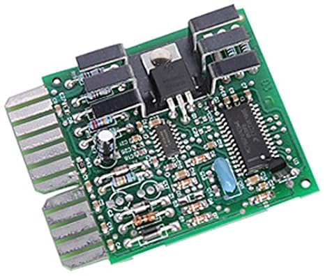
www.amazon.com/dp/B007Q128PG/ref=nav_tim..._encoding=UTF8&psc=1
Please Log in or Create an account to join the conversation.