P0122 TPS GM 4.3 / [FIXED!!]
KOEO measured .14v on 5v ref. wire(gray) and .03 to .1 v on signal wire(blue) when throttle moved slowly. This is measured on a multi meter. Ground is good and measures 40 mili volts. Truck starts and runs, but fault is constant and immediately comes back when cleared. Idle is high and throttle is a bit sluggish like you'd expect from a bad TPS. I watched the TPS videos, but they all start with a good 5v reference. I'll rewatch.
Question: Is the sensor good because I see a voltage change, even though it is way too low? Where should I be looking to see where my full 5 volts went? Will they come back when I put a new TPS in or should I be looking at a short in the ref wire. BTW, the instrument cluster gauges are all pegged waaay past their limits. Could that be related?
Thanks!
Please Log in or Create an account to join the conversation.
Please provide with year make and model so we can review the wiring schematic, and see what else is on there.
Please Log in or Create an account to join the conversation.
No 5v when unplugged. I've yet to see if the MAP has 5V. I forgot to mention that I also had a P1406(EGR pintle) fault code. I pulled it and it was not clogged up (just recently had the IM off and thoroughly cleaned the passage too. I looked at the diagram and fuel sender gauge module and the EGR share a gray (reference?) wire. Possible reason all the gauges are pegged??
I have measured voltage at all the listed 5v. ref. wires at the VCM (pins 12 and 21 on the WHITE connector with KOEO) and I'm only getting less than a volt. I have a known good computer. I put it in, and the condition is the same but did not have time to test it's 5v pins. Highly doubt I have two bad computers though. I'll test it tonight.
Thanks.
Please Log in or Create an account to join the conversation.
- matt.white
-

- Offline
- Elite Member
-

- Posts: 220
- Thank you received: 29
Please Log in or Create an account to join the conversation.
- Posts: 4443
- Thank you received: 968
This one covers testing a tps on another GM vehicle, hope it helps.
There's another one demonstrating the test Georg is describing with a resistor. That's a real good test, you can use a test light to substitute the resistor if you must.
Im curious to see how the 5v ref circuit looks with the known good pcm considering you happen to have one and it won't cost you anything to try it.
"Ground cannot be checked with a 10mm socket"
Please Log in or Create an account to join the conversation.

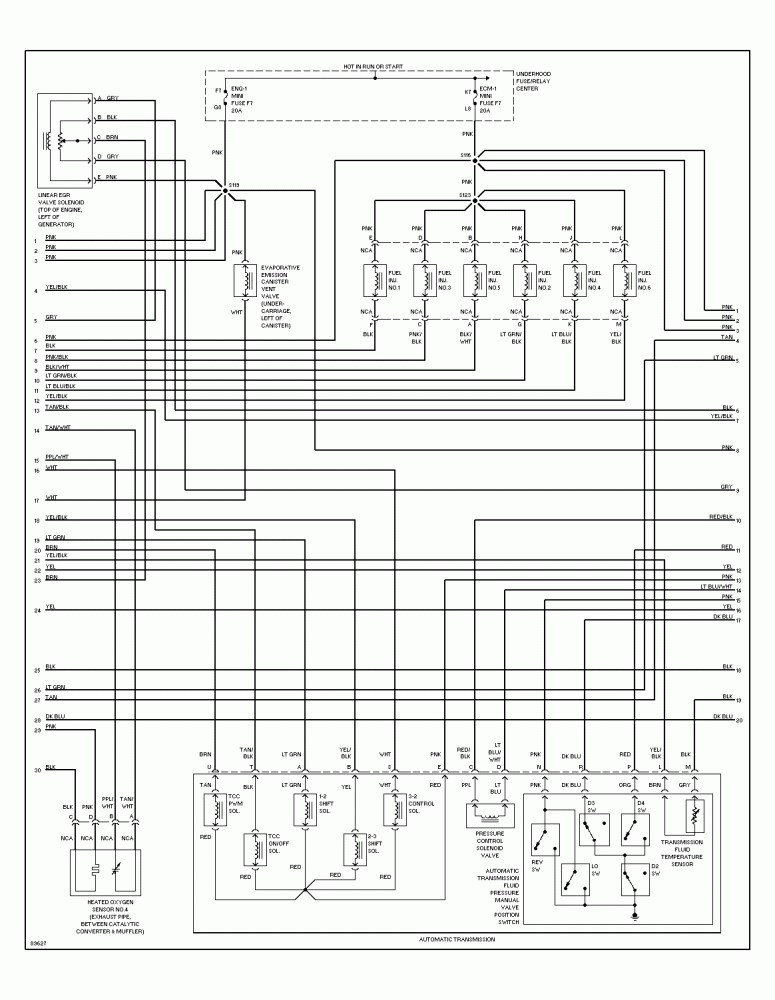
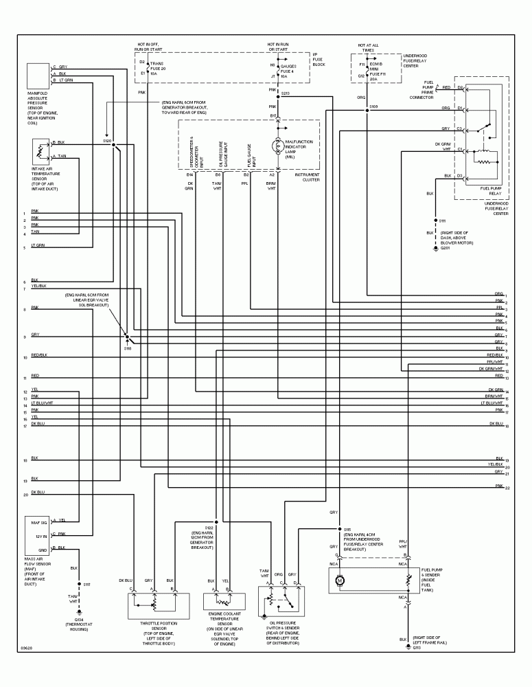
I'm using Mitchell1diy diagrams. There are 4 pages of diagrams and I'll try to link them here. Not sure if they will work. On page 4, at the right most portion of the whole diagram you can see the two 5v ref. pins (12 & 27). They are in the WHITE connector. There are 4 connectors on this VCM (WHITE,BLUE,RED,BLACK). This diagram(page 4) contains the WHITE (top)(pins1-32) and BLACK (bottom) (pins 1-24)connectors. Oh there is a 5th connector a 4 pin BLACK square, but it is just a loop through for the service circuit provider. Is that for a scanner connection??
<edit>I found a way to post the entire set of 4 diagrams. They should be laid out L to R(1-4) if you print them out.
")
Page #1
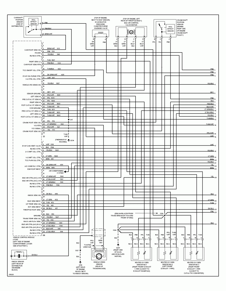
Page #2
Page #3
Page #4
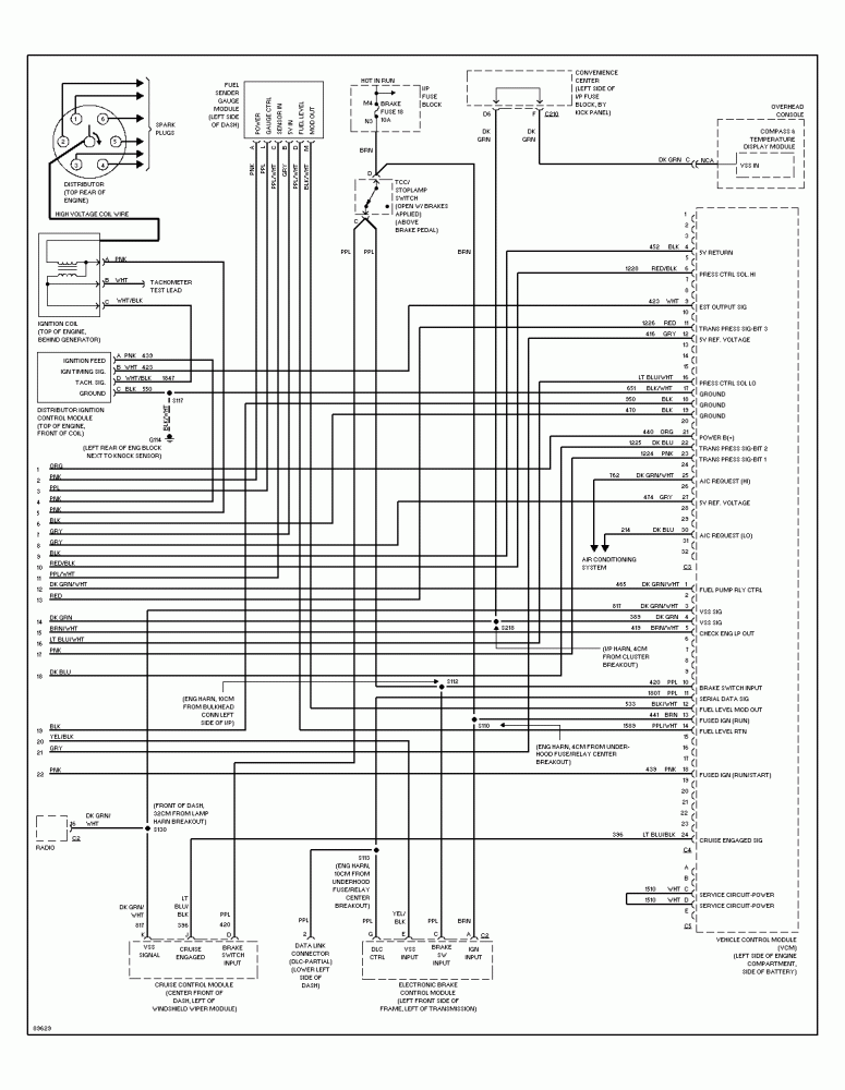
Computer
Please Log in or Create an account to join the conversation.
- Posts: 4443
- Thank you received: 968
I would start by checking for 5 volts on another sensor. If you still don't have it, time to look for a shorted circuit to ground with the ohm meter.
Of course powers and grounds at the VCM are suspect it the 5v ref doesn't check out, but your vehicle runs...
Those computers are notorious for connector issues and pin fitment problems. I've had to repin more than a couple connectors on that style VCM.
It's not popular with many Tech's, but if I don't find 5v at more than one sensor, I like to go ahead and cut the 5v wire coming right out of the vcm and check voltage there. If you got nothing, check computer power and grounds, (and check the connector for bent pins or corrosion),then if all that checks, it's computer time.
If you do have 5v at the computer after cutting the wire, then you need to start looking for a shorted sensor, or possibly a shorted out partly shorted wire to ground.
"Ground cannot be checked with a 10mm socket"
Please Log in or Create an account to join the conversation.
Please Log in or Create an account to join the conversation.
- ScannerDanner
-

- Offline
- Administrator
-

- Religion says do, Jesus says done!
- Posts: 938
- Thank you received: 486
Don't be a parts changer!
Please Log in or Create an account to join the conversation.
Please Log in or Create an account to join the conversation.
Noah wrote: If you're a premium member or if you have the book, there's lots of material covering the 5v ref circuit. This is part 1 of a 3 part series involving a Jeep which, although exhibits different symptoms, does not have 5v at the tps. It kind of walks you through Paul's thought process when the ref circuit is down.
I would start by checking for 5 volts on another sensor. If you still don't have it, time to look for a shorted circuit to ground with the ohm meter.
Of course powers and grounds at the VCM are suspect it the 5v ref doesn't check out, but your vehicle runs...
Those computers are notorious for connector issues and pin fitment problems. I've had to repin more than a couple connectors on that style VCM.
It's not popular with many Tech's, but if I don't find 5v at more than one sensor, I like to go ahead and cut the 5v wire coming right out of the vcm and check voltage there. If you got nothing, check computer power and grounds, (and check the connector for bent pins or corrosion),then if all that checks, it's computer time.
If you do have 5v at the computer after cutting the wire, then you need to start looking for a shorted sensor, or possibly a shorted out partly shorted wire to ground.
Ok, so some more work yielded not much progress, well maybe a bit. So, I checked for 5v ref. on other sensors. All are within 1/100 of a volt. Right around .12v. Measured this at every sensor(EGT,TPS,Fuel Gauge,MAP) on both the 5v circuits(I understand they are all really one, but with two outs of the computer). Measured TPS and has linear resistance with no hiccups in ramp up or down.
TPS- Gray(ref.) .14v
Black(gnd.) 100mv
Blue(sig.) .05v
MAP: Black(gnd.??) .37v
Lt. Green (sig.) .0v
Gray (ref.) .12v
I back probed and measured voltage on both reference wires at the WHITE VCM plug (pins 12 and 27 at the computer) and the low voltage is the same as is measured at each sensor. I unplugged each sensor and had the voltmeter watched...no change. 12.4 v measured TO the computer at the B+ input pin 21(WHITE connector orange wire). No evidence of damaged/corroded pins on VCM or expanded plug pins.
As mentioned above I have a spare computer. I installed it and all the measurements are the same. The odd thing came when I went to start it using this "good" computer. The engine barely sputtered, and would not run. I put the original computer back in and it runs and idles well, but not perfect(slight stutter upon revs). Hard P0122 still there and will not clear. 2 bad computers...broken differently??
I know you mentioned testing the reference line for a short with an ohm test. Forgive me, and I know this should be 101 type stuff, but exactly how do you do that? Embarrassed to say I don't know. I'm sure paul has a video of it somewhere..I'll look too.
As usual, thanks to all for any input. Very close to the nuclear option now...
Please Log in or Create an account to join the conversation.
Given the voltage measurements you have at pins 12 and 27 at the VCM, I'm really surprised you only getting a TPS code right now! Like Paul said, having low voltage suggests a short, yet the van runs. I've clipped the 5V reference wire close to the PCM before, and I think it's perfectly valid when chasing problems like this.
I'm wondering if you're not chasing some green corrosion in the VCM connector, causing a voltage drop right at the VCM. Maybe have a careful look at the female pins in the connector, or even consider taking that pin out of the connector for a closer inspection?
Please Log in or Create an account to join the conversation.
Yeah it is. None of that old thread we were working on could be migrated I was told. I forgot to mention it was the same problem child.
I had a bit of help from a shop and they told me "oh, it's the spider that's shorting things" and once the multi pin plug was disconnected from the injector (this has Central multi point) the short goes away. (BTW I could swear I did disconnect the EFI plug when I was trying to diag. the short, but I could have not had the key on or some other bonehead move as I was chasing my tail seeing as I really new at all this.)
Great I said. I Got a new spider(it was needing to be replaced anyway) and when I put the new one in and buttoned it up, the short was gone. I figured all is good. Turn the key on and the pump springs to life and we have DLC com, and it appears that the ECM-1 circuit is perfectly fine. Crank and it starts, but now I get the P0122 code and an EGR pintle code and a slightly rough rev. I pulled the EGR and checked it over put it back in and that code went away. We pick up the story over here on the new site.
So when I clip that wire(5V ref. GRAY) what am I looking for and where do I measure it at? I don't own a scanner btw. I guess before I do that, I'll put a tracer on that wire and hunt for a short.
The connectors look brand new with absolutely no corrosion. I'm in Southern CA and I think it rained about 9 months ago...maybe
") Corrosion is not one of our bigger problems. Heat is though.
Corrosion is not one of our bigger problems. Heat is though. Please Log in or Create an account to join the conversation.
- Posts: 4443
- Thank you received: 968
Scanner Danner has an awesome video, I think on a cobalt maybe? Checking for a 5v short to ground... I gotta do some searching to find it, I'll try to post it up tonight.
"Ground cannot be checked with a 10mm socket"
Please Log in or Create an account to join the conversation.
- Posts: 4443
- Thank you received: 968
As mentioned above I have a spare computer. I installed it and all the measurements are the same. The odd thing came when I went to start it using this "good" computer. The engine barely sputtered, and would not run. I put the original computer back in and it runs and idles well, but not perfect(slight stutter upon revs). Hard P0122 still there and will not clear. 2 bad computers...broken differently??
You need to do a security relearn procedure before the van will start with the other VCM.
It takes some time, about 30 minutes. Sometimes it doesn't take and you need to do it again...
basically, turn the key to the ON position (without cranking). The security lamp will illuminate and stay lit for about 10 minutes. When it switches off, turn the key off and wait 5 seconds.
Then turn the key to the ON position again, wait for the lamp to go out again, key off for 5 seconds again.
Then, turn the key to the ON position again. If the lamp comes on, then shuts off, the van will start. If not, just ANOTHER 10 minutes until the lamp goes off.
So that's 3 ten minute on cycles. After that, when you turn the key on, the security lamp should illuminate for a couple seconds, then go out. The van should start.
If the lamp stays illuminated, it won't start.
"Ground cannot be checked with a 10mm socket"
Please Log in or Create an account to join the conversation.
I just came back in and am just now reading you instructions about cutting the 5v ref. wires. After prodding/poking/moving/wiggling every bit of harness I could lay my hands on, that .15-.16 of a volt was about as solid as the Hoover Dam. Did not move at all. I also could not find any breaks or abrasion at any point(visible) on the harness. There is talk over on the Astro forum of a fault on the backside of the compartment side pass through. I've yet to figure out how to remove it, but wiggled the crud out of that area to no avail. I'll see if I can find a link to my post over there. I might have posted it on that other thread. It was a 12v power feed to the VCM though.
Here is the link to the thread, hope it works. Down about 1/2 way on page 1.
www.astrosafari.com/viewtopic.php?f=43&t=100745
Please Log in or Create an account to join the conversation.
- Posts: 4443
- Thank you received: 968
Here's the cobalt video I was thinking of. I re watched it to make sure it was the one. Unfortunately, he didn't get to the point of checking the 5 volt reference circuit for a short to ground.
Pretty much, with the sensors disconnected and the VCM disconnected, put one lead of the OHM meter to battery NEG, and the other lead to the 5v circuit at the VCM connector. The only acceptable reading here would be OL kOhms. Or 0 continuity. Hope that makes sense.
"Ground cannot be checked with a 10mm socket"
Please Log in or Create an account to join the conversation.
Noah wrote: Here's the cobalt video I was thinking of. I re watched it to make sure it was the one. Unfortunately, he didn't get to the point of checking the 5 volt reference circuit for a short to ground.
Pretty much, with the sensors disconnected and the VCM disconnected, put one lead of the OHM meter to battery NEG, and the other lead to the 5v circuit at the VCM connector. The only acceptable reading here would be OL kOhms. Or 0 continuity. Hope that makes sense.
It does. I'll try tonight. Thanks.
Please Log in or Create an account to join the conversation.
Noah wrote:
As mentioned above I have a spare computer. I installed it and all the measurements are the same. The odd thing came when I went to start it using this "good" computer. The engine barely sputtered, and would not run. I put the original computer back in and it runs and idles well, but not perfect(slight stutter upon revs). Hard P0122 still there and will not clear. 2 bad computers...broken differently??
You need to do a security relearn procedure before the van will start with the other VCM.
It takes some time, about 30 minutes. Sometimes it doesn't take and you need to do it again...
basically, turn the key to the ON position (without cranking). The security lamp will illuminate and stay lit for about 10 minutes. When it switches off, turn the key off and wait 5 seconds.
Then turn the key to the ON position again, wait for the lamp to go out again, key off for 5 seconds again.
Then, turn the key to the ON position again. If the lamp comes on, then shuts off, the van will start. If not, just ANOTHER 10 minutes until the lamp goes off.
So that's 3 ten minute on cycles. After that, when you turn the key on, the security lamp should illuminate for a couple seconds, then go out. The van should start.
If the lamp stays illuminated, it won't start.
This is a '97, I don't ever remember having a "security" light. I'll try it though. The van starts with one of the computers, it just has a P0122 code and super low ref. voltage.
Please Log in or Create an account to join the conversation.
- ScannerDanner
-
- Offline
- Administrator
-
- Religion says do, Jesus says done!
- Posts: 938
- Thank you received: 486
Don't be a parts changer!
Please Log in or Create an account to join the conversation.