[FIXED] 2005 Mazda 3S - Throttle Response Problem
- jcascel1
-
 Topic Author
- Offline
- Junior Member
-

- DIY'er not a Pro
- Posts: 38
- Thank you received: 7
Thanks for your perseverance and encouragement. I’ll pull myself together. lolI've still got ideas bouncing around in my head, so I might keep posting. Please don't feel obligated to answer until you're ready to come back to this one.
Yes, exactly! That’s why I decided to do it, others specifically reported success on the 05’s with 11’ Fusion engines! I did my homework, took my time, didn’t skimp on buying new parts, consulted with someone who has done 2.3 swaps, etc,.The really frustrating part is that this swap is supposed to work!
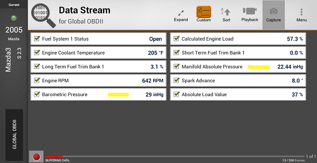
Checked this just a few minutes ago. Yes, BARO here correctly reads 29inHg at all times. MAP changes. Cold engine, KOEO, MAP reads 29.53inHg. Idling warm, MAP reads ~22inHg.They agree? I need to do some research, but my understanding is that this BARO sensor should read atmospheric pressure at all times. If there's vacuum connected to the BARO sensor, then that could be part of the problem.
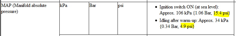
Mitchell online service manual states:
MAP should read – KO 15.4psi / Idle 4.9psi.
MAP actually reads – KO (29.53inHg ) 14.5psi / Idle (22.4inHg) 11.0psi!
I thought that a measure of the correct operation of the MAP is that it matches the BARO cold engine off. I used that as one of my checks but missed this difference at idle.
Nothing at all is connected to the BARO except the electrical connector. Its sensing orifice is open to the atmosphere. If I recall, the currently installed MAP sensor is from the 2.5. FWIW, RockAuto shows Airtex Wells part numbers are the same for this sensor.
I do feel better. Sorry for getting all negative.If it makes you feel better, I have seen catalysts survive stuff like this. It's life has probably been reduced, but it may not be completely useless yet.
Screenshot showing BARO vs MAP warmed up at idle. Also shows drastically improved fuel trims with 2.3L injectors.
Thanks,
John
Please Log in or Create an account to join the conversation.
- jcascel1
-
Topic Author
- Offline
- Junior Member
-
- DIY'er not a Pro
- Posts: 38
- Thank you received: 7
But, I think the MAP sensor may possibly explain the 35% reading? This system has both a MAP and MAF sensor, and we know already that the engine runs the same way without the MAF. With the engine showing 9" inHg at idle, the MAP is reading the same, and relaying this to the PCM. Lower vacuum means more load, which is probably driving the Engine Load reading up. This may also account for the skewed MAF g/s reading, if that PID is calculated between the MAF and MAP readings.
Just speculating here based on your excellent observations. Way out of my league but worth a try. LOL
So, on one hand, I’m wondering if the flow dynamics of the 2.5L intake are so different that it impacts the MAP/MAF reading enough to double it? Although Mazda’s IMRC system only seems to operate briefly at startup and high rpm’s, overall the flow might be much different.
On the other hand, given that the IMRC operates at startup (recall me mentioning that the IMRC actuator withdraws under vacuum moving the flaps at startup until the engine warms) this in effect acts like a choke. The Mazda PCM might expect very different inputs even though I still have the actuator/solenoid connected. It works, but the PCM still isn't seeing other inputs that it expects relative to flows. That is to say, slowing the air flow down.
This might explain a problem that is new with the 2.5L installed. The startup/warmup routine is missing. By this I mean that the 2.5L does not seem to recognize that the engine is cold. At cold start the rpms go to around 1000 for a second or two then just drop and the engine is left at sub idle till it struggles through the warmup period. The 2.3L PCM is counting on the flaps at startup (choke effect) but they aren't there to slow or affect air flow.
This IMRC effect is totally missing on the 2.5L manifold.This startup routine may be accounted for by the Fusion 2.5L PCM's open loop strategy since they wisely have no IMRC flaps to rely on! The Mazda 2.3L PCM doesn't know what to do without the flap system and the different air flow dynamics.

Hmmm, could the 2.3L intake be the key?
Thanks,
John
Please Log in or Create an account to join the conversation.
- jcascel1
-
Topic Author
- Offline
- Junior Member
-
- DIY'er not a Pro
- Posts: 38
- Thank you received: 7
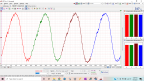
I compared this to a known good on iATN, and it agrees with yours.
Thanks very much for taking the time to do that! It's a great relief to know it's good.
FWIW, I'm calling the timing tool manufacturer tomorrow to ask about the notch in the 2.5 crank weight. Although my correlation waveform checks out good, I'm curious about that notch and what it's for. Might help to know.
I've talked with two other folks about this problem. One guy makes the 2.3 to 2.5 intake manifold adapter and the other makes the TB adapter that I bought. They have done these swaps. The first thing they both asked me about was the timing ring on the intake cam. Both were stumped by the elevated MAF/MAP and engine load anomalies. Oh well!
I've ordered the intake adapter since at some point I think putting the 2.3 intake and all of its IMRC gizmos is going to be necessary. Could be wrong but want to keep moving forward. Thanks!
Thanks,
John
Please Log in or Create an account to join the conversation.
- jcascel1
-
Topic Author
- Offline
- Junior Member
-
- DIY'er not a Pro
- Posts: 38
- Thank you received: 7
I've been thinking about the 2.5l injectors also. Would they contribute to a rich condition beyond the PCM's ability to control? While technically I assume they must be rated at a higher flow rate, would they necessarily realize their full potential under the 2.3l engine managment system, even with the 2.5l MAF installed?
then I foolishly said:
However, Would injectors and challenges with fuel trims contribute to the ultra low engine vacuum readings of <10inHg?
Sorry Noah, that was a dumb thing for me to say! Be patient with me, I'm just a diyer!
BTW, swapping in the 2.3 injectors made a significant difference in the trims at idle. So, thanks for bringing it up.
Thanks,
John
Please Log in or Create an account to join the conversation.
- Noah
-
- Offline
- Moderator
-

- Posts: 5038
- Thank you received: 1119
jcascel1 wrote: Noah said:
I've been thinking about the 2.5l injectors also. Would they contribute to a rich condition beyond the PCM's ability to control? While technically I assume they must be rated at a higher flow rate, would they necessarily realize their full potential under the 2.3l engine managment system, even with the 2.5l MAF installed?
then I foolishly said:
However, Would injectors and challenges with fuel trims contribute to the ultra low engine vacuum readings of <10inHg?
Sorry Noah, that was a dumb thing for me to say! Be patient with me, I'm just a diyer!
BTW, swapping in the 2.3 injectors made a significant difference in the trims at idle. So, thanks for bringing it up.
Nothing dumb or foolish at all sir, and certainly nothing to apologize for!
Trust me, i learn TONS every day. I may not be the shiniest wrench in the box, but I'm pretty sure I'm in the right drawer (don't know when these screw drivers moved in though.. :dry: )
I'm glad the injectors improved trims. I've been thinking about this intake adapter these other guys are using on their swaps. What is is for exactly? I mean, if someone is going through the trouble of making them and selling them, they must be kind of important.
Does it just allow you to retain the functionality of the IMRC? I noticed you had to do some clever rigging to keep the PCM happy about not using it any more.
That probably what I would have done too. "Buy more parts!? No way! More zip-ties maybe..."
Please Log in or Create an account to join the conversation.
- jcascel1
-
Topic Author
- Offline
- Junior Member
-
- DIY'er not a Pro
- Posts: 38
- Thank you received: 7
Ah yes, they make them and sell them and of course they work on every swap! Well, I’m learning a good lesson or five with this swap.I've been thinking about this intake adapter these other guys are using on their swaps. What is is for exactly? I mean, if someone is going through the trouble of making them and selling them, they must be kind of important.
Two adapters are sold for this swap. One is a 2.3 intake manifold to 2.5 cylinder head adapter. The 2.5 head has taller ports and the 2.3 intake leaves gaps. Many amazingly say that they simply use gasket maker to seal things up. (This I’m learning is one of many swap stories that honestly I’d just have to see to believe!)
I recently purchased one of these adapters since my stubborn desire to keep the 2.5 intake manifold has got to come to an end! I’m more and more convinced that the 2.3 PCM just can’t handle the airflow difference that the 2.5 intake manifold has. Maybe I’m wrong but given that all else is okay except MAP/MAF/Load I think it’s becoming more and more clear.
I felt that by keeping the 2.5 intake and injectors I’d be able to exploit the improved performance of the 2.5 with its allegedly better flowing head. It made sense to me, ya know, more air from the intake, more corresponding fuel from the bigger 2.5 injectors and the engine is happy. Well, I think the engine is indeed happy but the PCM is throwing a wrench in the works! I’m just a diyer so I’m most likely just running my mouth but we shall see I guess. lol
Next there is a 2.3 TB to 2.5 intake manifold adapter. The 2.3 TB must be used with the 2.5 because the 2.5 TB not only has a different bolt pattern but is incompatible with the 2.3 wiring harness and PCM (five pins v six) plus has no coolant jacket. Swappers are now reporting that a 2010 Mazda CX7 TB is a direct working fit on the 2.5 intake manifold.
The adapter plate that I bought has 3 tapped holes drilled through it which can become a vacuum source. I put a nipple on one source which I use for the IMRC control that is remaining and must operate to keep the PCM happy.Does it just allow you to retain the functionality of the IMRC? I noticed you had to do some clever rigging to keep the PCM happy about not using it any more.
The rigging actually only consists of mounting the Variable Tumbler actuator somewhere where it can still operate. The other solenoid only needs to remain connected to the harness. So, not too bad really.
I made a video of my current quandary and posted it on YT. In it you can see several of the things I’ve talked about and a couple of my troubleshooting steps. There is another video with some details of what's involved in this swap as well. The videos are lame but I'm reaching out to others who may be thinking about this swap. Generally speaking it's my impression that they would mostly be people like me who are adventurous diyers who just want to get their vehicles back on the road. On the other hand, perhaps I can inspire some to take after Paul in that they don't have to be parts swappers but instead better diagnosticians!
Thanks,
John
Please Log in or Create an account to join the conversation.
- Noah
-
- Offline
- Moderator
-
- Posts: 5038
- Thank you received: 1119
Please Log in or Create an account to join the conversation.
- jcascel1
-
Topic Author
- Offline
- Junior Member
-
- DIY'er not a Pro
- Posts: 38
- Thank you received: 7
Is there some kind of throttle calibration or relearn procedure for either motor?
If there is it's a well kept secret. Generally, the only thing people say is that you let it run for 30 minutes and just driving it will relearn it. No mention of it in the service manual, Mitchell, or AllDataDIY. Nothing available on the Encore regarding relearns. Nothing on the Vantage or anywhere else!
However, there is a reference in the FSM to something related to drive cycle adaptive relearn of some sort. Never could make sense of it plus you need to be able to rev the engine in order to go through the steps!!
FordTechMakuloco, of YT fame, states that a TB relearn on the Ford's can be done with the old disconnect the negative battery terminal and short it to the positive terminal for one minute trick. But, that's for Ford PCM's.
FWIW, when I first fired this swap up, after I had bled the cooling system, I let it idle for almost 45 minutes while I checked for leaks, etc,. No difference. The damn thing has a learning disability!
Thanks,
John
Please Log in or Create an account to join the conversation.
- jcascel1
-
Topic Author
- Offline
- Junior Member
-
- DIY'er not a Pro
- Posts: 38
- Thank you received: 7
FWIW, I'm calling the timing tool manufacturer tomorrow to ask about the notch in the 2.5 crank weight. Although my correlation waveform checks out good, I'm curious about that notch and what it's for. Might help to know.
Uhm, no luck. He said, "no, the sides of the weight should be flat. Never seen a mark of any kind on the weights. Sounds like a spot where they may have done some balancing work. You know, like the mark that a drill bit would make?"
God damn it, NO! And it just happens to line up absolutely perfectly with the timing peg when it's installed in the side of the block and the number one piston just happens to be at TDC! No friggin' way!
The mystery notch. This swap just keeps surprising. Ugh.
Thanks,
John
Please Log in or Create an account to join the conversation.
- Tyler
-
- Away
- Moderator
-
- Full time HACK since 2012
- Posts: 6126
- Thank you received: 1542
Watched the video, you weren't kidding! That engine does not want to rev up at all. Gotta love how PCM's and grounds are the boogeymen for difficult performance issues. :lol:
I might have missed it in between, but did you ever get the chance to put a screwdriver in the #1 cylinder and verify that the piston agrees with the cam timing slots? It's been nagging at me since the weekend, wondering if we still have some fundamental timing issue. Though, I wonder if this thing would idle at all if the timing were that far out. :blink:
The other thing I had on my mind was static compression testing. I don't know what the specification is, but I'd expect around 150 PSI. My problem with that is, if it comes out low, then I don't know that we gained a lot of information.
BTW, if you still care to take a shot at ignition waveforms, we'd be happy to help you make sense of them. Your Vantage Pro should handle primary voltage waveforms perfectly.
Please Log in or Create an account to join the conversation.
- Tyler
-
- Away
- Moderator
-
- Full time HACK since 2012
- Posts: 6126
- Thank you received: 1542
jcascel1 wrote: Uhm, no luck. He said, "no, the sides of the weight should be flat. Never seen a mark of any kind on the weights. Sounds like a spot where they may have done some balancing work. You know, like the mark that a drill bit would make?"
God damn it, NO! And it just happens to line up absolutely perfectly with the timing peg when it's installed in the side of the block and the number one piston just happens to be at TDC! No friggin' way!
The mystery notch. This swap just keeps surprising. Ugh.
I found a decent picture of the way this weight is supposed to look, while reading about timing setup on a 2.5L. I find it tomorrow and post it here.
Please Log in or Create an account to join the conversation.
- jcascel1
-
Topic Author
- Offline
- Junior Member
-
- DIY'er not a Pro
- Posts: 38
- Thank you received: 7
Nice find. I couldn't find one at all today.That Mazda timing document you shared was amazing. However, nowhere in it does it mention the tensioner or a single thing about eliminating chain slack between the gears before putting the timing cover back on! Kind of shocked me as a diyer but probably is a no brainer for a pro.I found a decent picture of the way this weight is supposed to look, while reading about timing setup on a 2.5L. I find it tomorrow and post it here.
No, not yet. I'm pulling the plugs out tomorrow to have a look at them and so I'll verify TDC tomorrow.I might have missed it in between, but did you ever get the chance to put a screwdriver in the #1 cylinder and verify that the piston agrees with the cam timing slots? It's been nagging at me since the weekend, wondering if we still have some fundamental timing issue. Though, I wonder if this thing would idle at all if the timing were that far out. :blink:
Can't argue with you there. Would a relative compression be good enough even if done with the Vantage? It's not the greatest for this but is adequate if I can get the scope set up right before the battery dies on me.The other thing I had on my mind was static compression testing. I don't know what the specification is, but I'd expect around 150 PSI. My problem with that is, if it comes out low, then I don't know that we gained a lot of information.
But, if it comes out good, then I'd feel a lot better about timing.
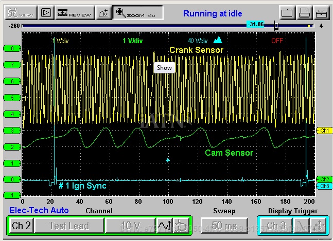
Definitely at some point. It would be great to have some backup on interpretation. I'm not convinced that the single cylinder ignition setting on the Vantage is best to use. Confusion here is that the FSM states to set the scope up at 10v/div and expecting around 40vdc. Really!? The Vantage setting sets the scope to 50kv/div. That's why I think I got those crazy waveforms earlier. Maybe not? So, scope on DCV, one lead to coil, other lead to battery ground. Unless you can recommend a better Vantage option?BTW, if you still care to take a shot at ignition waveforms, we'd be happy to help you make sense of them. Your Vantage Pro should handle primary voltage waveforms perfectly.
Thanks,
John
Please Log in or Create an account to join the conversation.
- Tyler
-
- Away
- Moderator
-
- Full time HACK since 2012
- Posts: 6126
- Thank you received: 1542
jcascel1 wrote: Can't argue with you there. Would a relative compression be good enough even if done with the Vantage? It's not the greatest for this but is adequate if I can get the scope set up right before the battery dies on me.
No, sorry sir, not in this case. The problem with a relative compression test is that, if our problem changes how all cylinders breathe, then it won't show any problems. However, you could verify ignition timing with the relative compression and an ignition sync if you wanted. This would show if we're getting spark at the right time or not. This video demonstrates the idea:
Definitely at some point. It would be great to have some backup on interpretation. I'm not convinced that the single cylinder ignition setting on the Vantage is best to use. Confusion here is that the FSM states to set the scope up at 10v/div and expecting around 40vdc. Really!? The Vantage setting sets the scope to 50kv/div. That's why I think I got those crazy waveforms earlier. Maybe not? So, scope on DCV, one lead to coil, other lead to battery ground. Unless you can recommend a better Vantage option?
Ah yeah, I understand your confusion here! I think the Mazda material is talking about scoping the primary ignition waveform, while the single cylinder ignition preset on the Vantage is for a secondary ignition trace. The Vantage preset is actually just a converted voltage scale, probably around 5V or so. That's why your waveforms never look good.
Your lead connections are perfect. Just turn the DCV scale up to around 100V total (or 10V/div, whatever) and trigger as needed. The 100V is a good starting point, and may require fine tuning depending on the height of the inductive spike.
So, I got some phone pictures of the crank weight, hopefully they make sense:


It looks to me like both show the crank weight machined down so it'll come up flat against the timing pin. If your crank has been drilled into, then WTF?
Please Log in or Create an account to join the conversation.
- jcascel1
-
Topic Author
- Offline
- Junior Member
-
- DIY'er not a Pro
- Posts: 38
- Thank you received: 7
Got it. Good idea.No, sorry sir, not in this case. The problem with a relative compression test is that, if our problem changes how all cylinders breathe, then it won't show any problems. However, you could verify ignition timing with the relative compression and an ignition sync if you wanted. This would show if we're getting spark at the right time or not. This video demonstrates the idea:
Okay.Ah yeah, I understand your confusion here! I think the Mazda material is talking about scoping the primary ignition waveform, while the single cylinder ignition preset on the Vantage is for a secondary ignition trace. The Vantage preset is actually just a converted voltage scale, probably around 5V or so. That's why your waveforms never look good.
Thanks.Your lead connections are perfect. Just turn the DCV scale up to around 100V total (or 10V/div, whatever) and trigger as needed. The 100V is a good starting point, and may require fine tuning depending on the height of the inductive spike.
Yes, I'm familiar with that. There is a video on YT which actually gives a very nice view of the timing peg/crank weight relationship. The guy has a 2.3 with the timing cover and (i think) oil pan removed. Thanks for the photos.So, I got some phone pictures of the crank weight, hopefully they make sense:
Uhm, yeah, I think WTF sums this swap up rather well. Never did I imagine that this would be happening. I was being so careful and, I thought, thorough.It looks to me like both show the crank weight machined down so it'll come up flat against the timing pin. If your crank has been drilled into, then WTF?
I did not set the timing on this engine. I went out of my way to pay someone, who has done it before, to come and do it for me. It was worth it for me to let some one else do it in order to avoid problems. I watched the guy do it. He insisted on using an impact to tighten the crank bolt. He insisted that the impact would tighten the bolt to even higher torque than the recommended manual method. Hell, he even left the timing tools in place when he tightened the bolt! Compounding the issue, the plugs that came with the engine were frozen in place. The carbon must have solidified over time as the engine sat. I tried to get them out to no avail. They cam out instantly once the engine ran for a bit however. Point is that I was not able to pull a plug to verify TDC after timing was set. Although I think he got it right it would have been nice to have seen TDC and all the other timing clues.
So, my theory is that he did not tighten the bolt enough with the impact. I never did feel good about it. The timing must have changed at first startup. FML
My timing check video is almost uploaded. I'll post it here shortly thereafter. You guys can watch it and hopefully tell me that I am mistaken and the timing is actually fine. After, you fail to tell me that, I'll give you my final thoughts on the 2.5L keyless crankshaft engines and how utterly useless a cam crank correlation is on an engine of that design!
Thanks,
John
Please Log in or Create an account to join the conversation.
- jcascel1
-
Topic Author
- Offline
- Junior Member
-
- DIY'er not a Pro
- Posts: 38
- Thank you received: 7
After thinking about it, it would appear that a cam/crank correlation waveform is useless on these engines.
Looking at the Mazda timing technical document it is clear that during the timing process you are not actually timing the crankshaft, rather, you are actually timing the crankshaft pulley! The crank can still be off even if the pulley is timed correctly - 9th tooth at the center of the CKP sensor.
Insane as it seems, as far as the PCM is concerned, as long as it sees that the CKP sensor is generating a signal based off of the timing wheel and that the CMP sensor is also generating a signal off of the cam timing wheel - and they are in sync, then it's happy. So what if the crank has shifted and the #1 cylinder isn't actually at TDC!!
Otherwise, How is it possible that scan data can show the timing to be set properly at exactly the specified 8 degrees BTDC when the crank isn't actually at #1 TDC?
No timing related codes. The only give away is that the engine runs like crap.
Am I crazy, Or is this a legitimate possibility?
Thanks,
John
Please Log in or Create an account to join the conversation.
- Interrupt
-

- Offline
- New Member
-

- Posts: 16
- Thank you received: 3
Adding unnecessary complexity is the Manufacturers attempt to ensure there products are taken to the dealers...!!!
I reckon you've cracked it. I would have liked to see the cam alignment in respect to tdc.
For a DIYer you've done an awesome job of testing and explaining your testing , processes and thought pattern GOOD JOB!
I think next time time it yourself I'm sure you'll do a better job!!
Please Log in or Create an account to join the conversation.
- jcascel1
-
Topic Author
- Offline
- Junior Member
-
- DIY'er not a Pro
- Posts: 38
- Thank you received: 7
Lucky you! The high was 17F here today. No outside work took place!Don't envy you in that weather!!! I take my hat off to you working out there! :ohmy: It's 7am here and it's a toasty 25'c.
Yes agree. Here though I'm actually entertaining the thought.Adding unnecessary complexity is the Manufacturers attempt to ensure there products are taken to the dealers...!!!
I'll report on that at some point since I'm certainly curious as well.I reckon you've cracked it. I would have liked to see the cam alignment in respect to tdc.
Thanks, that means a lot to me. The goal from the beginning was to learn along the way. I'm a bit embarrassed though since timing should have surely been the first or at least second thing I checked. I put too much trust in the guy who timed it. Learned a lesson on that one.For a DIYer you've done an awesome job of testing and explaining your testing , processes and thought pattern GOOD JOB!
Thanks. We shall see. This swap is full of surprises! lolI think next time time it yourself I'm sure you'll do a better job!!
Thanks,
John
Please Log in or Create an account to join the conversation.
- Tyler
-
- Away
- Moderator
-
- Full time HACK since 2012
- Posts: 6126
- Thank you received: 1542
You're absolutely right in your thinking about the timing setup on this one. I was thinking along these lines earlier, but wasn't positive in my understanding:
Tyler wrote: So, with this (horrible) timing design, it's possible to have the cams line up with each other, have the cam and crank tone wheels line up with each other, and still have the crankshaft out of time, correct? This would possibly result with the pistons being out of time with the cam events, and still not detectable by the PCM. Am I understanding this correctly? :huh:
After your Mazda, I think I'll have to adjust my thinking. It's not that the cam/crank relationship checks the timing of the camshaft and crankshaft, it checks the timing of the camshaft tone wheel and the crankshaft tone wheel. If anyone is interested, this is the known good I compared to from iATN:
I know that I said a relative compression test wouldn't work in this case, but I'm starting to wonder if we should have done it sooner...? Since the PCM is firing the coils to what IT thought was TDC, then the timing problem may have shown up. Also curious if the compression test would have failed. Not that you need to go do these tests! Just speculating out loud.
jcascel1, I feel like I owe you an apology, sir. :blush: I wasted a bunch of your time going over stuff like the TAC, BARO and Engine Load, when I should have narrowed in on timing as soon as I saw the vacuum reading (which I also should have suggested sooner).
Interrupt is right, you should be happy with how this went! I know it was a struggle, but I think you can be confident that just about any shop you took this to would have wasted all kinds of your $$$ and time getting to the problem. You put way more effort and thought into this than the majority of techs out there would have.
Also:

:lol: :lol: :lol:
So, what's the next move? Going to re-time it yourself?
Please Log in or Create an account to join the conversation.
- Noah
-
- Offline
- Moderator
-
- Posts: 5038
- Thank you received: 1119
I like your line of thought there, I'd like to see what that would have looked like.I know that I said a relative compression test wouldn't work in this case, but I'm starting to wonder if we should have done it sooner...? Since the PCM is firing the coils to what IT thought was TDC, then the timing problem may have shown up. Also curious if the compression test would have failed. Not that you need to go do these tests! Just speculating out loud.
Looks like you were right on. Pretty goofy set up, I've seen other guys do them, but have never had to do one myself.Tyler wrote:
So, with this (horrible) timing design, it's possible to have the cams line up with each other, have the cam and crank tone wheels line up with each other, and still have the crankshaft out of time, correct? This would possibly result with the pistons being out of time with the cam events, and still not detectable by the PCM. Am I understanding this correctly? :huh:
100% Great job.Interrupt is right, you should be happy with how this went! I know it was a struggle, but I think you can be confident that just about any shop you took this to would have wasted all kinds of your $$$ and time getting to the problem. You put way more effort and thought into this than the majority of techs out there would have.
Please Log in or Create an account to join the conversation.
- jcascel1
-
Topic Author
- Offline
- Junior Member
-
- DIY'er not a Pro
- Posts: 38
- Thank you received: 7
YOU owe ME and apology? Holy crap, if it wasn't for you and your encouragement and affirmation I would be nuts by now. I really, really needed someone to work with me at the time and you were right there to help! Thanks so much!jcascel1, I feel like I owe you an apology, sir. :blush: I wasted a bunch of your time going over stuff like the TAC, BARO and Engine Load, when I should have narrowed in on timing as soon as I saw the vacuum reading (which I also should have suggested sooner).
Yup, you nailed it. Even though I knew that that had to be true, I couldn't come to terms with it yet and especially how a PCM couldn't know. CKP sensor = crank position right! Mind blown. Early on I did the cam crank correlation. Once it matched the one from my other 2.3 I moved on and figured the problem was elsewhere, TB, APP, intake, injectors, etc,. We all got fooled I guess.Tyler wrote:
So, with this (horrible) timing design, it's possible to have the cams line up with each other, have the cam and crank tone wheels line up with each other, and still have the crankshaft out of time, correct? This would possibly result with the pistons being out of time with the cam events, and still not detectable by the PCM. Am I understanding this correctly? :huh:
Tricky ground here. Might one condemn an engine/head if a compression test fails but the crank is out? Wonder if it's happened. Rookie in me wouldn't immediately go to timing but instead to a mechanical like rings, valves, gasket, etc,. Good lesson for me.Also curious if the compression test would have failed.
Thanks so much! That means a lot. Once I had watched two or three of Paul's videos, I was inspired. Long, long, way to go but getting there.100% Great job.
Oh yeah! I have to fabricate a tool to hold the pulley first. As far as I can see, I can get the pulley off with the engine in. Then I can attempt to pull out the diamond coated lock washer to replace it. That might end up being the biggest challenge of all to be honest. Makes me nervous since it could potentially drop into the pan. Might have to abandon the idea and just use the one that's in there. New bolt though.So, what's the next move? Going to re-time it yourself?
Here's the plan: Pull the plugs out. Time the cams, find crank TDC, and then time the pulley. Have a rod in #1 cylinder as TDC visual verification. I'll mark the rod somehow for future reference. I'll lock the pulley down while holding it but with the timing tools still in place. I happen to have an impact that has a max torque of 75ft/lbs. Shouldn't be a problem. I'll remove the timing tools and rotate the engine 2x to verify no issues. Bring everything back to TDC using the rod and cam slots/lobes as my TDC verification.
To finish, even though I'll be holding the pulley for the final additional 90 degrees of torquing, I plan to use the transmission and brakes (and a helper) to hold the crank. Correct me here if I'm wrong!
With everything at TDC I'll put the trans in first and leave it. I'll have my helper hold the brakes on while I get the final 90 degrees of tightening. In my mind this will help hold everything in place and will also make it much easier for me to hold the pulley and tighten the crank bolt the final 90. Then, some more engine rotations for verification and peace of mind.
When I'm done, I'll fire it up and let it idle for a bit to relearn. If it warms up normally (rpms up as expected when cold) I'll know I'm in good shape. I'll look at the MAF/MAP/LOAD for some good news and then give it a sweet throttle blip!
Anyway, that's the plan!
Thanks,
John
Please Log in or Create an account to join the conversation.