2009 dodge challenger rt with 5.7 engine no crank, no start and no communication
- ChallengerDude
-
 Topic Author
- Offline
- Junior Member
-

- Posts: 26
- Thank you received: 4
Please Log in or Create an account to join the conversation.
- ChallengerDude
-
Topic Author
- Offline
- Junior Member
-
- Posts: 26
- Thank you received: 4
Please Log in or Create an account to join the conversation.
- ChallengerDude
-
Topic Author
- Offline
- Junior Member
-
- Posts: 26
- Thank you received: 4
Please Log in or Create an account to join the conversation.
- Monde
-
- Offline
- Elite Member
-

- Posts: 220
- Thank you received: 43
Assuming is never a good thing.
Please Log in or Create an account to join the conversation.
- ChallengerDude
-
Topic Author
- Offline
- Junior Member
-
- Posts: 26
- Thank you received: 4
I've gone through the wiring but don't see any other damage. The rebuilt PCM I tried has some corrosion on the pins. Not sure if it's also not working but the rebuilding is going to send another unit. There was or still is a rodent running around in the car. Not sure if there is some unseen wiring damage. But tried using the powerprobe short finder but didn't find anything.
Please Log in or Create an account to join the conversation.
- ferris48
-

- Offline
- Premium Member
-

- Posts: 129
- Thank you received: 47
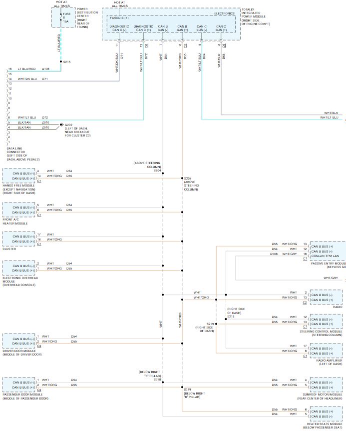
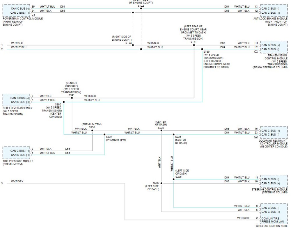
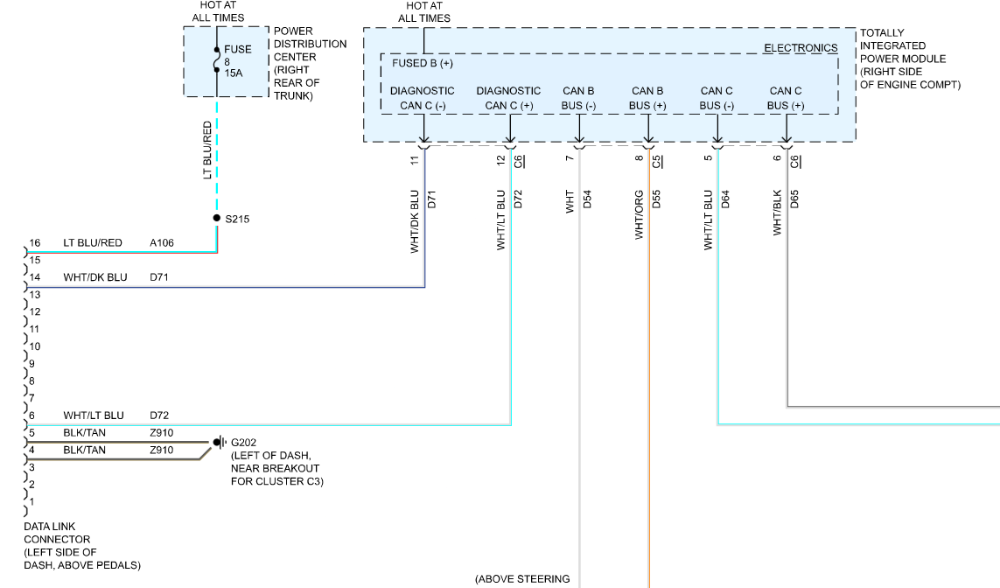
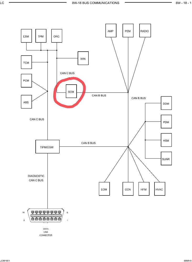
I believe the 60 ohm reading you took was of the TIPM, and not the CAN-C. Check for 60 ohms at the CAN-C connector at the TIPM, not the DLC. The 2 terminating resistors are in the PCM and WIN.The dlc power and grounds check out okay and the can connectors have 2.5v and 60ohm across.
You can experiment if this assertion is true or not. Measure across the DLC for 60 ohms. Then unplug the PCM or WIN, whichever is easier to get to. The DLC resistance reading of 60 ohms should change. Does it?
Please Log in or Create an account to join the conversation.
- ferris48
-
- Offline
- Premium Member
-
- Posts: 129
- Thank you received: 47
Please Log in or Create an account to join the conversation.
- Monde
-
- Offline
- Elite Member
-
- Posts: 220
- Thank you received: 43
Yeah, If i use obdlink, the can b bus is accessible but not the can c bus. Get a U0001 can c bus error.
I've gone through the wiring but don't see any other damage. The rebuilt PCM I tried has some corrosion on the pins. Not sure if it's also not working but the rebuilding is going to send another unit. There was or still is a rodent running around in the car. Not sure if there is some unseen wiring damage. But tried using the powerprobe short finder but didn't find anything.
In my opinion, If the pcm were the cause of the CAN C bus error, you would most likely have a lot of echoes on the CAN lines if the terminating resistance were missing unless the terminating resistance were fine, but the transceiver were bad. When you unplugged the pcm for can lines testing, you would have the communication back as it would be the reason that the bus were down. The pictures you posted did not show echoes. The quality of the pictures were in part due to the scope itself.
Assuming is never a good thing.
Please Log in or Create an account to join the conversation.
- ChallengerDude
-
Topic Author
- Offline
- Junior Member
-
- Posts: 26
- Thank you received: 4
Please Log in or Create an account to join the conversation.
- ferris48
-
- Offline
- Premium Member
-
- Posts: 129
- Thank you received: 47
The can bus lines at the TIPM measure 60ohms. The DLC shows 62ohms and no change with the PCM and WIN unplugged. The battery was disconnected.
That's great information, thanks for testing that.
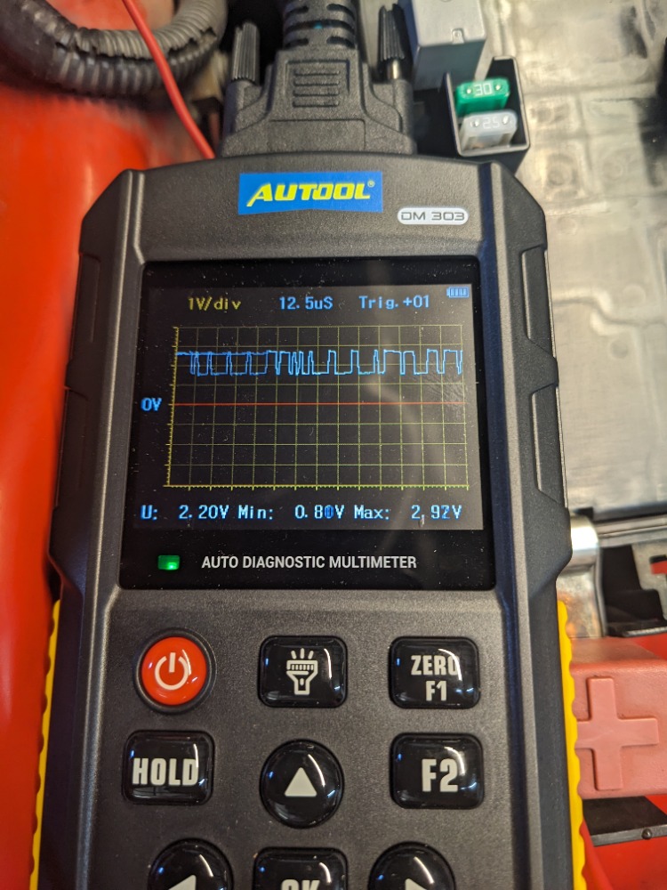
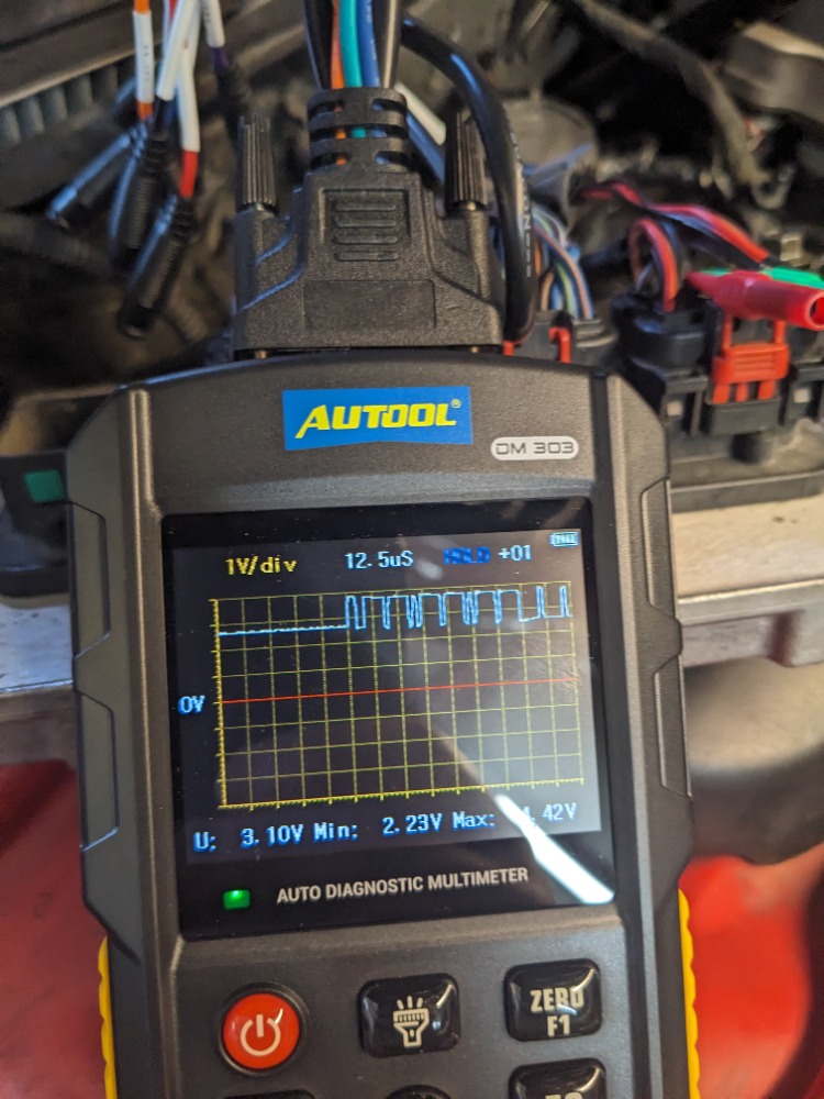
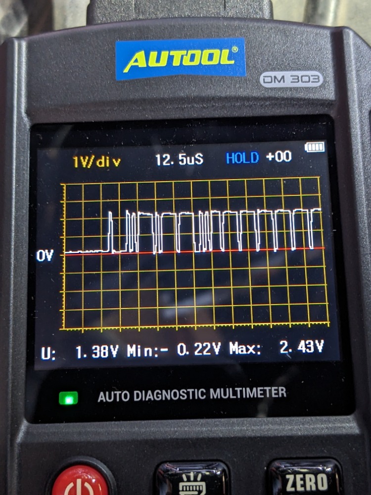
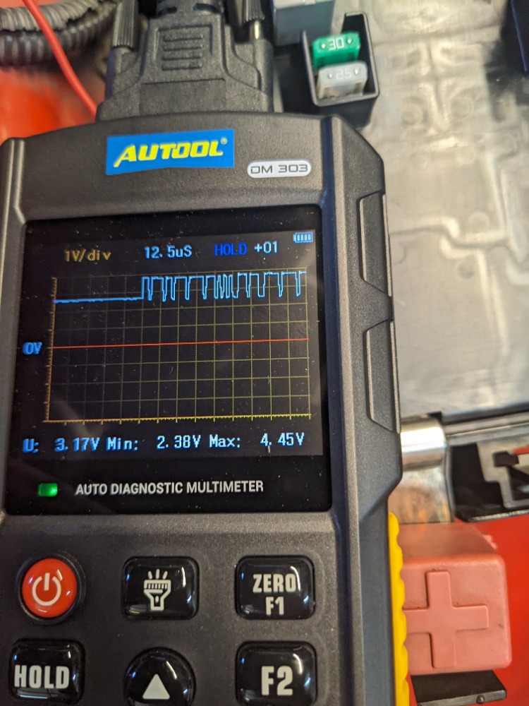
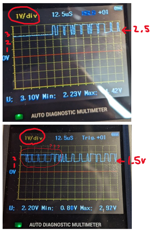
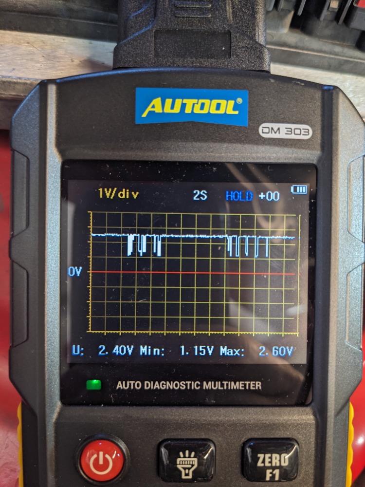
For can high look for bias voltage of 2.5V and the signals jumping up to 3.5V. The first picture is obviously can high.
The second picture where I put question marks. Did the bias voltage drop down to 1.5V from 2.5V ?
The question marks I drew, I think that's image ghosting because of how fast the signal is going across the screen.
What does can low look like. It should be biased around 2.5V and signals should drop down to 1.5V.
You need to stare at these to find any abnormalities.
Please Log in or Create an account to join the conversation.
- ferris48
-
- Offline
- Premium Member
-
- Posts: 129
- Thank you received: 47
Can the steering Control module talk to CAN C ? Or rather, is it throwing a lost com to pcm?If i use obdlink, the can b bus is accessible
It's on CAN-C and CAN-B.
Please Log in or Create an account to join the conversation.
- Monde
-
- Offline
- Elite Member
-
- Posts: 220
- Thank you received: 43
Assuming is never a good thing.
Please Log in or Create an account to join the conversation.
- ChallengerDude
-
Topic Author
- Offline
- Junior Member
-
- Posts: 26
- Thank you received: 4
Please Log in or Create an account to join the conversation.
- ChallengerDude
-
Topic Author
- Offline
- Junior Member
-
- Posts: 26
- Thank you received: 4
Please Log in or Create an account to join the conversation.
- ChallengerDude
-
Topic Author
- Offline
- Junior Member
-
- Posts: 26
- Thank you received: 4
I've unplugged some of the easy ones so far. ABS, TPM and shift modules.
Please Log in or Create an account to join the conversation.
- ChallengerDude
-
Topic Author
- Offline
- Junior Member
-
- Posts: 26
- Thank you received: 4
Please Log in or Create an account to join the conversation.
- ChallengerDude
-
Topic Author
- Offline
- Junior Member
-
- Posts: 26
- Thank you received: 4
I checked powers and grounds on the etc connector before but could check it with the scope.
Please Log in or Create an account to join the conversation.
- Monde
-
- Offline
- Elite Member
-
- Posts: 220
- Thank you received: 43
The way that Bernie was showing in the video
Assuming is never a good thing.
Please Log in or Create an account to join the conversation.
- ChallengerDude
-
Topic Author
- Offline
- Junior Member
-
- Posts: 26
- Thank you received: 4
I did try jumping the 2 sensor wires for the etc after seeing that at the pcm they had 4v and 0v and at the etc they had 4v and .8v. But the connection at the pcm may not have been good with the back probe.
Please Log in or Create an account to join the conversation.
- Monde
-
- Offline
- Elite Member
-
- Posts: 220
- Thank you received: 43
(Jump the can lines with the 2 wires)
Iwith an open etc wire you should have 5v at the pcm , not 4 Check again to make sure
Assuming is never a good thing.
Please Log in or Create an account to join the conversation.