Help us help you. By posting the year, make, model and engine near the beginning of your help request, followed by the symptoms (no start, high idle, misfire etc.) Along with any prevalent Diagnostic Trouble Codes, aka DTCs, other forum members will be able to help you get to a solution more quickly and easily!
Nissan Frontier 1998 manual trans and 2.4 liter has a high idle and no comms
The diagram that I provided to you is the only one I see for your truck in my little Alldata program. I don't see any pin 74 in it. If the wire colors from your truck matches the wiring diagram. I would say, use it.
If you find no continuity between 7 and 69, make sure you have good connection and find the open if connection is good.
Yes, pin 69 and 7 should have continuity. The thing is that you keep questioning the wiring diagram. If you could find another wiring diagram, it would be very helpful. Sometimes, we may have to check and clean the connectors to avoid any poor contacts.
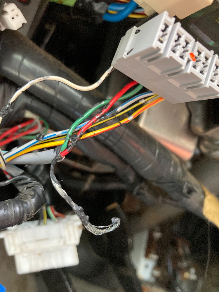
The wire colors seem to match the diagram. Red/ green( battery voltage)Black ( ground) Light green/red (K-line) Black/ Yellow (ground)
As you have the wires in front of you, check the K-line again if you see they match. If it shows OL, which I doubt because you had voltage on the K-line at some point during testing.
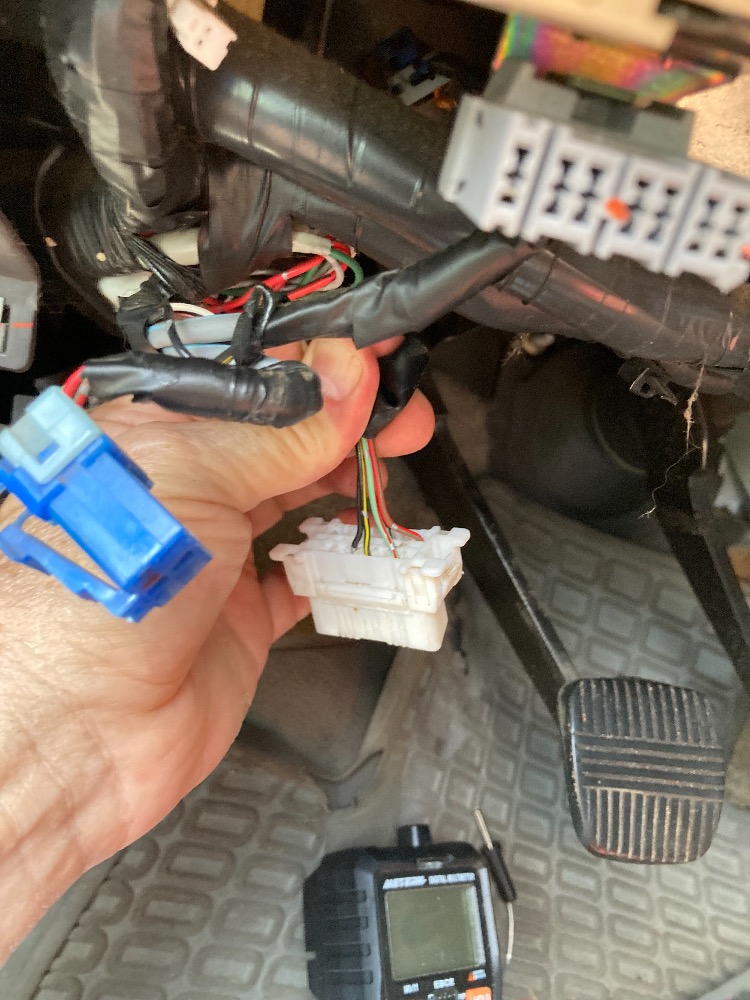
the k line at the OBD2 diagnostic port goes to or has continuity with pin 74 at the ECU. Im looking for the connection plugs shown on the pin out you sent for the ECU, that go between each of the diagnostic ports because they changed the dashboard/instrument panel and may have got the plugs crossed. I wish I knew the location for the two connectors on these lines. I may have to pull the dash apart to find them…
Earlier I think I confused pin 69 and pin 74 at the ECU connector because they are difficult to distinguish and there are no numbers on the holes in the connector. Do you have any information on the location of connector 14 from the ECU pin out diagram you sent?
Unfortunately, no. You can go by wire color. I will post the ECU pin layout.
The file exceed the limit. If you look at the bottom of the diagram I posted. you should see the ECM pin layout. Pin 68 and 69 (second row)are above pin 74.
Checking the K line at the female ECU plug has been difficult to determine which pin is which. I took the back off the female plug and I can now see which pin is 69. It shows 1 ohm resistance to the OBD2 port for the k line (pin 7). What I thought was pin 74 was pin 69. My bad. I'll check the powers and grounds again since I may have got the pins wrong on these...I'll send pics.
I took out the ECU and it appears a couple capacitors are not good so I am going to replace the capacitors that test bad using an ESR meter. Three of them have high resistance based on the ESR meter readings. I should have that done next week.
Replaced all 4 electrolytic capacitors and reinstalled ECU and the idle came down to just over 1,000 rpm when cold. Also, the rapid clicking of the under-dash solenoid no longer occurs when the key is turned on... whatever that was, it seemed to be associated with the poor engine operation. I'll test drive it and update this.
none of the modules communicate and therefore no codes. It still runs at high idle, apparently the ECM capacitor changes did not improve anything. Any suggested next steps...
That was the wrong question to ask since you can't communicate with any modules. As far as the no communication issue, I really can't think of anything else that can cause it. You only have to deal with the K line, the 2 grounds at the DLC.
You are supposed to have .2 v -14v on the K line with engine idling and scanner disconnected. The 2 grounds can be checked for opens by checking their resistance to ground. If there are no wiring issues, you may need to go to local shops and see if they can communicate with their scanners. Some of them will do it for free.
Verify that the pins are not bent, corroded and make sure that they fit well in the connectors.
Thanks for the adivise. I’ll check for bent pins at the ECU connector, and check the grounds. I have several scanners and none communicate. This vehicle has a Nissan Consult connector so I will try to get that software to try it.
To me, if you have 12v on pin 16, 0.2 v-14v on pin 7 at the DLC and the ECM with engine running and scanner disconnected and have continuity to ground on the 2 ground wires, you should be able to communicate with the ECM. If you cant, you just have to check powers and grounds at the ECM before calling it bad.
Have you ever thought of sending the ECM out for testing? It may just be a bad ECM.
I've not heard about sending the ECU out for testing. Tell me how to send the ECU out for testing? Is it expensive to have one tested? Can you reference a few companies that you know about? If bad would you recommend a referbished ECU?