*** Restricting New Posts to SD Premium Members ONLY *** (09 May 2025)

Just made a new account? Can't post? Click above.

Help us help you. By posting the year, make, model and engine near the beginning of your help request, followed by the symptoms (no start, high idle, misfire etc.) Along with any prevalent Diagnostic Trouble Codes, aka DTCs, other forum members will be able to help you get to a solution more quickly and easily!

Nissan Frontier 1998 manual trans and 2.4 liter has a high idle and no comms

  • Chad
  • Chad's Avatar
  • Offline
  • Moderator
  • Moderator
  • I am not a parts changer.
More
1 year 1 month ago #66324 by Chad

im having trouble with posting to the forum. I don't know what my user ID is so I am unable to send a request to support.
 
That post went through. What kind of problems are you having?
 

"Knowledge is a weapon. Arm yourself, well, before going to do battle."
"Understanding a question is half an answer."

I have learned more by being wrong, than I have by being right. :-)

Please Log in or Create an account to join the conversation.

  • Marti
  • Marti's Avatar Topic Author
  • Offline
  • Premium Member
  • Premium Member
More
1 year 1 month ago #66331 by Marti
My previous post had not gone through and I was logged out, perhaps I was on the forum too long? How long before one get's logged out?

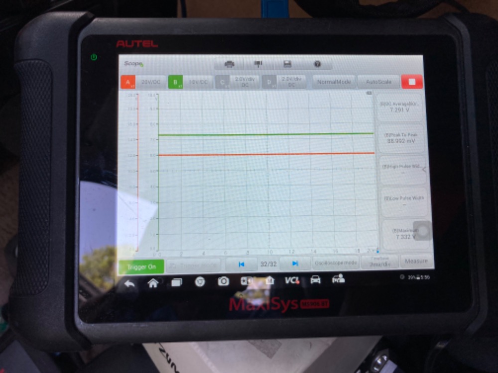
My update was that I hooked up a OBD2 breakout box with scanner and an oscilloscope on the line 7. When the scanner tried to ping all the modules, I was seeing about 7 volts on the line 7. I once saw the oscilloscope trace on line 7 go to about 12 volts and then back to 7 v. It also seemed to go to near 0 volts but that could have been a loose connection. I'll post some pics next

Please Log in or Create an account to join the conversation.

  • Marti
  • Marti's Avatar Topic Author
  • Offline
  • Premium Member
  • Premium Member
More
1 year 1 month ago #66345 by Marti
Some photos show oscilloscope readings on K line
Attachments:

Please Log in or Create an account to join the conversation.

  • Marti
  • Marti's Avatar Topic Author
  • Offline
  • Premium Member
  • Premium Member
More
1 year 1 month ago #66355 by Marti
I was not successful posting the oscilloscope pics but they show a steady 7 volts on the K line. Perhaps I had the trigger set wrong, but at one point I saw some square waves pulling down to zero in a set of several square waves, but it could be less than 12 volts at the top of the square. None of my scanners can read any modules on the OBD2 diagnostic port. Although the Topdon Phoenix plus seemed to connect but could not talk to any module.

Please Log in or Create an account to join the conversation.

  • Chad
  • Chad's Avatar
  • Offline
  • Moderator
  • Moderator
  • I am not a parts changer.
More
1 year 1 month ago - 1 year 1 month ago #66362 by Chad
The K-line voltage on Pin #7 is low. To determine if the low voltage is due to a bad wire, or a bad ECM, move to the ECM connector. Disconnect the ECM connector and check for continuity (Ohms) to ground on Pin #7 of the OBDII port. There should be no continuity and the Ohm meter should read OL mΩ.  If that checks out, move back to the ECM connector and open the wiring harness. Access the wire on Pin #69. Find a place that will be easy to repair, and snip the K-line wire. Plug the connector back into the ECM and turn the key on. Check the voltage on the ECM side of the snip. If you, now, have 12 volts, there is a problem with the wire going to the OBD port that is pulling the voltage down. If you still read 7 volts, then check for battery voltage on the power supplies for the ECM on:
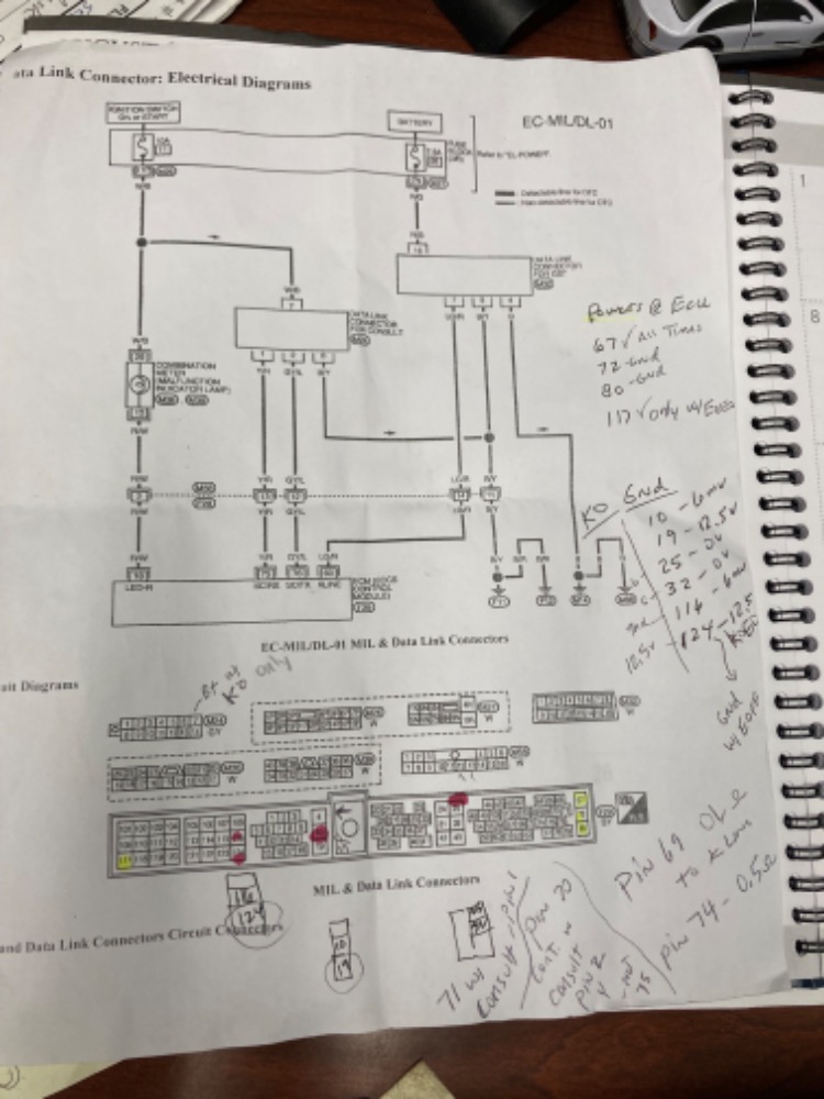
Pin #67 (Pink/Black)
Pin #72 (Pink/Black)
Pin #80 (Lt. Blue)
Pin #117 (Pink/Black)


Check for voltage one the Grounds of the ECM, as well:
Pin #10 (Black/Red)
Pin #19 (Black/Red)
Pin #25 (Black/Yellow)
Pin #32 (Black/Yellow)
Pin #116 (Black/Red)
Pin #124 (Black/Red)

Ground voltage should be less than 0.1 volt. Anything above that is a problem.  Do all of your voltage checks with the key on, or engine running.
If your Powers and Grounds are good, it's time to start pointing the finger at the ECM.

"Knowledge is a weapon. Arm yourself, well, before going to do battle."
"Understanding a question is half an answer."

I have learned more by being wrong, than I have by being right. :-)
Last edit: 1 year 1 month ago by Chad.

Please Log in or Create an account to join the conversation.

  • Marti
  • Marti's Avatar Topic Author
  • Offline
  • Premium Member
  • Premium Member
More
1 year 1 month ago #66366 by Marti
Thanks I'll do these tests. I know earlier a wiring diagram was posted for a newer Frontier with ABS so I hope you are instructing these tests based on a 1998 Frontier D22 with stick shift and no ABS. Just checking...

Please Log in or Create an account to join the conversation.

  • Marti
  • Marti's Avatar Topic Author
  • Offline
  • Premium Member
  • Premium Member
More
1 year 1 month ago #66367 by Marti
In the pic the green trace is the K-line
Attachments:

Please Log in or Create an account to join the conversation.

  • Marti
  • Marti's Avatar Topic Author
  • Offline
  • Premium Member
  • Premium Member
More
1 year 1 month ago #66369 by Marti
do you have pin outs on the ECU connector? I found no continuity on the K line with the ECU unplugged. The grounds on the OBD2 connectors both look good.

Please Log in or Create an account to join the conversation.

  • Marti
  • Marti's Avatar Topic Author
  • Offline
  • Premium Member
  • Premium Member
More
1 year 1 month ago #66370 by Marti
k line has no continuity to ground with ECU unplugged. I pulled out the ECU and will open to see if the capacitors look swollen or other signs of cracked solder joints.

Please Log in or Create an account to join the conversation.

More
1 year 1 month ago - 1 year 1 month ago #66371 by Monde
Are you opening the ECM because the K-line shows no continuity to ground? The K -line should not have continuity to ground. If it does, it is shorted to ground. You should have continuity when checking for opens: Meter in ohm setting, with one lead to each end.

Assuming is never a good thing.
Last edit: 1 year 1 month ago by Monde.
The following user(s) said Thank You: Lupe

Please Log in or Create an account to join the conversation.

  • Marti
  • Marti's Avatar Topic Author
  • Offline
  • Premium Member
  • Premium Member
More
1 year 1 month ago #66385 by Marti
I would like to check continuity from the K-line on the OBD2 connector pin 7, to the connector at the ECU but I need the pin out diagram to determine which pin on the connector is to the K-line. Does anyone have this pinout?

Please Log in or Create an account to join the conversation.

More
1 year 1 month ago - 1 year 1 month ago #66386 by Monde
pin 69

Assuming is never a good thing.
Attachments:
Last edit: 1 year 1 month ago by Monde.

Please Log in or Create an account to join the conversation.

  • Marti
  • Marti's Avatar Topic Author
  • Offline
  • Premium Member
  • Premium Member
More
1 year 1 month ago #66387 by Marti
Thanks for the pinout. I show 0.5 ohms from the diagnostic port pin 7 to the 69 pin on the ECU connector so that's a good circuit. Tomorrow I will reinstall the ECU and cut the light green/red K-line somewhere near the ECU and check that it puts out 12 volts.

Please Log in or Create an account to join the conversation.

More
1 year 1 month ago - 1 year 1 month ago #66388 by Monde
Before reinstalling the ECM, make sure that K-Line is not shorted to ground. Ohm either end to ground: Meter should read OL. I am pretty sure that the line is not shorted because you saw varying voltage on that wire. Since you have no opens on the K-Line, cutting the wire is going to be proven unnecessary. Just for your peace of mind, you can cut it.

Assuming is never a good thing.
Last edit: 1 year 1 month ago by Monde.
The following user(s) said Thank You: Chad

Please Log in or Create an account to join the conversation.

  • Marti
  • Marti's Avatar Topic Author
  • Offline
  • Premium Member
  • Premium Member
More
1 year 1 month ago #66389 by Marti
with the ECM out of the car, I checked powers and ground on the ECM connector with Key on. I found problems, the following ground pins had 12.5 volts: pin 19 and pin 124. Other grounds were good, but pins 10 and 116 were just a few millivolts. Also, for power feeds, only pins 67 and 117 had battery volts. Pins 72 and 80 had no power.

Please Log in or Create an account to join the conversation.

  • Marti
  • Marti's Avatar Topic Author
  • Offline
  • Premium Member
  • Premium Member
More
1 year 1 month ago #66390 by Marti
There is a ground on the right front of the engine somewhere the diagram says, that grounds the ECU pin 19 circuit. This pin on the ECU connector shows battery volts with the key on. Do you have any information on where exactly this ground is? The wire is black with a red line according to the diagram.

Please Log in or Create an account to join the conversation.

More
1 year 1 month ago - 1 year 1 month ago #66392 by Monde

with the ECM out of the car, I checked powers and ground on the ECM connector with Key on. I found problems, the following ground pins had 12.5 volts: pin 19 and pin 124. Other grounds were good, but pins 10 and 116 were just a few millivolts. Also, for power feeds, only pins 67 and 117 had battery volts. Pins 72 and 80 had no power.

I can't tell you where it is located. Also, pins 10,116,19 and 124 seem to share the same ground. If you get good ground on pin 10  and 116, the ground has to be good.


Assuming is never a good thing.
Last edit: 1 year 1 month ago by Monde.

Please Log in or Create an account to join the conversation.

  • Marti
  • Marti's Avatar Topic Author
  • Offline
  • Premium Member
  • Premium Member
More
1 year 1 month ago #66497 by Marti
Thanks for your help to this point. I was delayed working on the truck due to Hurricane Debbie. I'm back on it and hope to have something tomorrow to share.

Please Log in or Create an account to join the conversation.

  • Marti
  • Marti's Avatar Topic Author
  • Offline
  • Premium Member
  • Premium Member
More
1 year 1 month ago #66499 by Marti
I want to confirm that the given ECU pin out diagram is for my 1998 Frontier stick shift with 2.4 liter and air conditioning D22 version.  I rechecked continuity from the OBD2 connector pin 7 (k line) to pin 69 on ECU but show OL.  Actually ECU pin 74 showed continuity (0.5 ohm) to the k line pin 7.  Also saw wrong pins on the CONSULT connector to the ECU pins   See picture for readings of continuity 
Attachments:

Please Log in or Create an account to join the conversation.

  • Marti
  • Marti's Avatar Topic Author
  • Offline
  • Premium Member
  • Premium Member
More
1 year 1 month ago #66500 by Marti
I know the dash- instrument panel was replaced so possibly the 2  diagnostic connector (OBD2 and CONSULT 14 pin connector were wired wrong.  I never have had communication with scanners on either diagnostic connector since getting the truck.  Alternatively I’m given the wrong pin out diagram for the ECU?

Please Log in or Create an account to join the conversation.

Time to create page: 0.519 seconds