Help us help you. By posting the year, make, model and engine near the beginning of your help request, followed by the symptoms (no start, high idle, misfire etc.) Along with any prevalent Diagnostic Trouble Codes, aka DTCs, other forum members will be able to help you get to a solution more quickly and easily!
2003 Ford Taurus
- muni5310
-
 Topic Author
- Offline
- New Member
-

Less
More
- Posts: 1
- Thank you received: 0
8 years 11 months ago #8628
by muni5310
2003 Ford Taurus was created by muni5310
Hello,
I have a 2003 Ford Taurus with a V6 with a return-less fuel system, with a no start issue.
When I turn on the ignition and I check the fuel pressure regulation module, on the blue wire with the orange stripe I have 3.7 Volts with the key in the On position; and when cranking it goes too 2.5 V is this normal?
The issue I am having is the car would start sometimes not all the time and when it does start it would not run for more than 2-3 minutes with little or no acceleration and then it will shot off and it would be a while before it starts again.
Any suggestions would be appreciated.
Thanks and keep up the good work with your youtube page I have found it very useful many times.
Please Log in or Create an account to join the conversation.
- ScannerDanner
-

- Offline
- Administrator
-

- Religion says do, Jesus says done!
Less
More
- Posts: 975
- Thank you received: 500
8 years 11 months ago #8636
by ScannerDanner
Please Log in or Create an account to join the conversation.
- Tyler
-
- Offline
- Moderator
-

- Full time HACK since 2012
Less
More
- Posts: 6115
- Thank you received: 1539
8 years 11 months ago #8656
by Tyler
Replied by Tyler on topic 2003 Ford Taurus
Hey muni5310! All those videos Paul posted are fantastic for understanding Ford electronic returnless systems.
So I could get an idea of which wire the blue/orange wire is, I went to the wiring diagram:

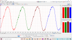
That's it in the lower right. This circuit is part of the command/monitor circuit the PCM and Fuel Pump Driver Module use to communicate back and forth. One wire will be the PCM's commanded fuel pump duty cycle, and the other will be the FPDM's status signal back to the PCM.
Without scoping both wires, it's tough to say which one is which. Because you noted the voltage change during cranking, I'm gonna say that it's normal, and reflecting the PCM's command to the FPDM to run the pump. For more info and scope captures off this FPDM system, check out this other thread on an intermittently starting Econoline") :
:
scannerdanner.com/forum/post-your-repair...4ford-e450.html#8554
Do you have access to a scope or scan tool? I can recommend some quick pump tests, depending on what you have available.
If this were me, I'd be watching the pump power and ground at the FPDM (white/red and black/pink) during the no start. White red should have power with the key on, and black/pink should be a pulsed ground when the pump is commanded on.
So I could get an idea of which wire the blue/orange wire is, I went to the wiring diagram:
That's it in the lower right. This circuit is part of the command/monitor circuit the PCM and Fuel Pump Driver Module use to communicate back and forth. One wire will be the PCM's commanded fuel pump duty cycle, and the other will be the FPDM's status signal back to the PCM.
Without scoping both wires, it's tough to say which one is which. Because you noted the voltage change during cranking, I'm gonna say that it's normal, and reflecting the PCM's command to the FPDM to run the pump. For more info and scope captures off this FPDM system, check out this other thread on an intermittently starting Econoline
:scannerdanner.com/forum/post-your-repair...4ford-e450.html#8554
Do you have access to a scope or scan tool? I can recommend some quick pump tests, depending on what you have available.
If this were me, I'd be watching the pump power and ground at the FPDM (white/red and black/pink) during the no start. White red should have power with the key on, and black/pink should be a pulsed ground when the pump is commanded on.
Please Log in or Create an account to join the conversation.
Time to create page: 0.284 seconds