Stumped- P1233 and occasional P1237- '04Ford e450
- hard.wired
-
 Topic Author
- Offline
- New Member
-

- Posts: 9
- Thank you received: 0
Vehicle: 2004 Ford e450 - Triton 6.8 V10
Trouble codes: P1233 and sometimes P1237
Symptoms: Variable - sometimes will require cranking 4-5 times before starting if sitting for several days. Will sometimes stall out right after engine starts, but will then start okay and engine runs fine after. Engine seems to run fine otherwise.
What has been changed so far: FPDM. Once with Dorman unit and once with Ford OEM part.
Recent troubleshooting: Fuel pressure good. Engine runs fine, no apparent problem with fuel pump. I have verified power and ground at FPDM. Checked for continuity and resistance at the FPDM control wire which goes to pin 40 of PCM and shows good continuity and resistance reading of 0.2-04 ohm.
Full history of this problem: Vehicle showed engine code P1233, so FPDM was changed with Dorman unit. After 4 hour trip to vacation destination, vehicle started losing power, stalled and was difficult to start. Finally, a crank no start condition. Vehicle was towed to garage and started right up. Garage let vehicle run for 1-2 hours and engine finally stalled out. Garage said faulty fuel pump. New fuel pump was put in, with bad fuel sending unit. Drove 4 hour home no problems, except P1233 code came back. Next day, crank no start. Cleaned all grounds that could be found under vehicle and engine starts fine. P1233 still showing after being cleared. Fuel pump changed with new Ford OEM fuel pump. Gas gauge now working and engine starts fine. P1233 code still showing after being cleared. Changed FPDM with OEM part. This brings us back to the current "Symptoms" and the "Recent Troubleshooting" detailed above.
Please Log in or Create an account to join the conversation.
- GeekDIYMechanic
-
- Offline
- Premium Member
-

Have you done voltage drop tests on both power and grounds? Continuity tests are useless to finding corrosion issues. Voltage drop tests will ensure the circuit can deliver the necessary current.
I would study your wiring diagrams associated to your FPDM and examine all grounds for this circuit. Vibration or heat could be your villain.
I suggest looking at the wiring harness going back to your pump from your cab. I think there is a connector somewhere around you cab. If you find it, perhaps do a votlage drop test from the pcm side and then the bed side. What I'm getting at is that many times these connectors get corrosion in them. So I would test before taking it apart. Your call.
Just keep looking; your persistence will pay off.
Please Log in or Create an account to join the conversation.
- cheryl hartkorn
-
- Offline
- Platinum Member
-

- Posts: 694
- Thank you received: 130
Please Log in or Create an account to join the conversation.
- Ben
-
- Offline
- Platinum Member
-
- Posts: 1098
- Thank you received: 215
Sent from my SM-N920P using Tapatalk
Please Log in or Create an account to join the conversation.
- Tyler
-
- Offline
- Moderator
-

- Full time HACK since 2012
- Posts: 6126
- Thank you received: 1542
Ford wrote: Electronic Returnless Fuel Systems (ERFS) utilize a Fuel Pump Driver Module (FPDM) to control fuel pressure. The PCM uses a Fuel Rail Pressure Sensor (FRP) for feedback. The PCM outputs a duty cycle to the FPDM to maintain the desired fuel rail pressure. During normal operation, the PCM will output a FP duty cycle from 5% to 51%. The FPDM will run the fuel pump at twice this duty cycle, e.g. if the PCM outputs a 42% duty cycle, the FPDM will run the fuel pump at 84%.
If the PCM outputs a 75% duty cycle, the FPDM will turn off the fuel pump. The FPDM returns a duty cycled diagnostic signal back to the PCM on the Fuel Pump Monitor (FPM) circuit to indicate if there are any faults in the FPDM.
If the FPDM does not out any diagnostic signal, (0 or 100% duty cycle), the PCM sets a P1233 DTC. This DTC is set if the FPDM loses power. This can also occur if the Inertia Fuel Switch is tripped.
If the FPDM outputs a 25% duty cycle, it means that the fuel pump control duty cycle is out of range. This may occurs if the FPDM does not receive a valid control duty cycle signal from the PCM. The FPDM will default to 100% duty cycle on the fuel pump control output. The PCM sets a P1235 DTC.
If the FPDM outputs a 75% duty cycle, it means that the FPDM has detected an open or short on the fuel pump control circuit. The PCM sets a P1237 DTC.
If the FPDM outputs a 50% duty cycle, the FPDM is functioning normally.
The P1237 code would suggest that FPDM powers/grounds are OK (otherwise, how could it send a signal to the PCM?), and that there's a pump problem. But, then there's the P1233, which points directly to a FPDM problem.
I have some captures of this system from a newer F-150 - different truck, same system. Green is fuel pump power, yellow is fuel pump control, red is the PCM's fuel pressure command, and blue is the FPDM's feedback. This was taken KOEO.
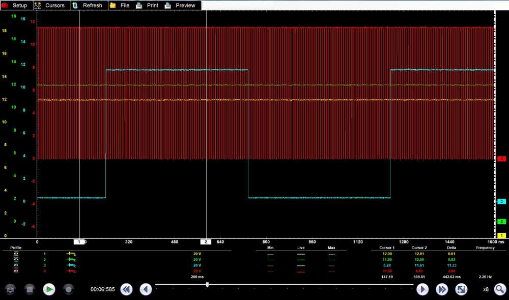
During cranking (and starting), those signals should look something like this:
Note the yellow trace starts pulsing, showing FPDM control of the pump. Blue keeps pulsing the whole time, which is good.
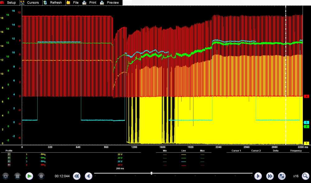
This next one is the same truck when it wouldn't start due to no fuel pressure.
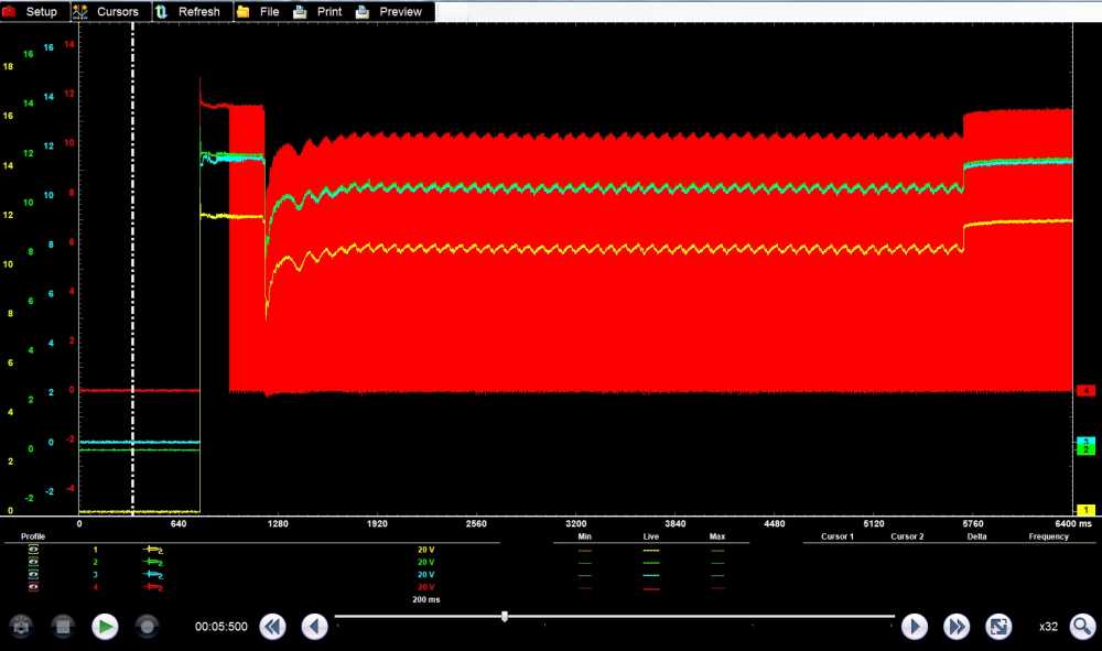
No signal on the blue (fixed high), and no control of the pump. The lack of activity on the blue trace is what the PCM is using to set the P1233 and P1237.
Please Log in or Create an account to join the conversation.
- hard.wired
-
Topic Author
- Offline
- New Member
-
- Posts: 9
- Thank you received: 0
Cheryl, I am not experiencing a consistent crank/no start at this time. Just occasional cranking 4-5 times before it will start. Should I just proceed with the load test on the ground then?
Thanks Tyler for posting the info from the service manual. So I was under the impression that a P1233 code just meant that the PCM did not receive a signal back from the FPDM. I was not considering intermittent ground/power issues. So that means a P1233 can be triggered by a lose of power or ground by the FPDM? I am a little confused now with your comment about the P1237 suggesting FPDM power/grounds are okay, but yet P1233 points to FPDM.
Please Log in or Create an account to join the conversation.
- Tyler
-
- Offline
- Moderator
-
- Full time HACK since 2012
- Posts: 6126
- Thank you received: 1542
hard.wired wrote: Thanks Tyler for posting the info from the service manual. So I was under the impression that a P1233 code just meant that the PCM did not receive a signal back from the FPDM. I was not considering intermittent ground/power issues. So that means a P1233 can be triggered by a lose of power or ground by the FPDM? I am a little confused now with your comment about the P1237 suggesting FPDM power/grounds are okay, but yet P1233 points to FPDM.
Sorry 'bout the confusion!
My thinking about the P1237 is that, since the FPDM has to send a 75% duty cycle for that code to set in the PCM, then the FPDM must have power and ground (at the time the code set, anyway). The feedback signal circuit must also be intact, otherwise the PCM would never see 75%.
But then there's the P1233, which indicates the FPDM signal was fixed low or high (0 or 100% duty cycle). That spells out an inop FPDM or wiring problem.
Anyway, since you've got a new OE FPDM and pump, I'd say the P1233 would be the code to follow. But, I have been wrong before! :lol:
Please Log in or Create an account to join the conversation.
- Ephratah
-

- Offline
- Senior Member
-

Hitting it with a Hammer is worth $5 knowing where to hit is worth $40
Please Log in or Create an account to join the conversation.
- Doc n2mx
-
- Offline
- Senior Member
-
- Posts: 44
- Thank you received: 10
I see that the guys have some great information for you and I thought I would just add a bit more to it.
I see that you tested only part of the system. You need to look at the rest of the inputs and controls.
Description: The powertrain control module (PCM) monitors the fuel pump monitor (FPM) circuit from the fuel pump driver module (FPDM). With the ignition ON, engine OFF or ignition ON, engine running the FPDM continuously sends a duty cycle signal to the PCM through the FPM circuit. The test fails if the PCM stops receiving the duty cycle signal.
Possible Causes: Inertia fuel shutoff (IFS) switch needs to be reset Open FPDM ground circuit Open circuit to FPDM PWR RLY Open FPDM PWR circuit Open or short FPM circuit (engine should start) Damaged IFS switch Damaged FPDM PWR RLY
Damaged FPDM Diagnostic Aids:
The PCM expects to see one of the following duty cycle signals from the FPDM on the FPM circuit: 1) 50% (500 ms on, 500 ms off), all OK. 2) 25% (250 ms on, 750 ms off), FPDM did not receive a fuel pump (FP) duty cycle command from the PCM, or the duty cycle that was received was invalid. 3) 75% (750 ms on, 250 off), the FPDM detected a concern in the circuits between the FPDM and the fuel pump. Application Key On Engine Off Key On Engine Running Continuous Memory
I hope this information helps the next thing you need to get is a proper wiring diagram and start testing.
Good luck.
Doc n2m
Please Log in or Create an account to join the conversation.
- hard.wired
-
Topic Author
- Offline
- New Member
-
- Posts: 9
- Thank you received: 0
In regards to the IFS switch, I thought these either work or they do not work? I have not had to reset that switch. Early tests show I am getting 12v there KOEO. How would one go about troubleshooting an intermittent problem from a damaged IFS switch or FPDM PWR relay? BTW, I do not have a scope, just a multimeter and power probe.
Please Log in or Create an account to join the conversation.
- Tyler
-
- Offline
- Moderator
-
- Full time HACK since 2012
- Posts: 6126
- Thank you received: 1542
hard.wired wrote: In regards to the IFS switch, I thought these either work or they do not work?
You'd think, right? :lol: I've never seen a switch go bad, but I have seen the pin contacts develop high resistance, or melt entirely.
How would one go about troubleshooting an intermittent problem from a damaged IFS switch or FPDM PWR relay? BTW, I do not have a scope, just a multimeter and power probe.
I think I'd keep it simple and just watch that white wire at the FPDM when it requires multiple starting attempts. Backprobe that pin, and hook up your meter/Power Probe/test light to watch voltage. If you see low voltage, then work your way back to the inertia switch or power relay. If you see steady voltage, then switch up to the FPDM ground and try again.
Please Log in or Create an account to join the conversation.
- hard.wired
-
Topic Author
- Offline
- New Member
-
- Posts: 9
- Thank you received: 0
Tyler wrote: I think I'd keep it simple and just watch that white wire at the FPDM when it requires multiple starting attempts. Backprobe that pin, and hook up your meter/Power Probe/test light to watch voltage. If you see low voltage, then work your way back to the inertia switch or power relay. If you see steady voltage, then switch up to the FPDM ground and try again.
I can try this, but I will only have a few shots at looking at the voltage as it usually will start after 5-6 attempts if sitting longer than a day. My fear is that I will not be able to recreate the crank/no start condition. It seems the code is pending after running for at least a few minutes, sometimes longer.
Please Log in or Create an account to join the conversation.
- hard.wired
-
Topic Author
- Offline
- New Member
-
- Posts: 9
- Thank you received: 0
cheryl hartkorn wrote: you need to be tapped into the circuit on the white wire at the driver module when it becomes a crank no start. see if your loosing a power feed from a failing fuel pump relay or an intermittent inertia shut off switch issue. also load the ground with a headlight bulb. that's where I would start.
I have done some preliminary testing on the FPDM. Here are the results.
1. FPDM input from inertia switch = battery voltage (KOEO)
2. Fuel pump feed = battery voltage (KOEO and KOER)
3. Fuel pump ground = battery voltage (KOEO) and close to 0 volts (KOER)
4. FPDM ground = 0 volts (KOEO) and 2.5-4.5 volts (KOER)
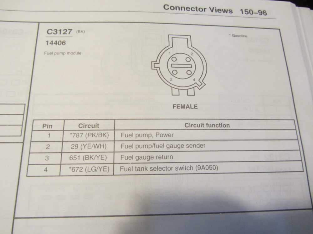
I believe test 4 above should give 0 volts with engine running, so I am not sure how to interpret this result. I also wanted to do voltage drop tests in the wiring at the fuel pump, but there is an extra connector on this vehicle between the FPDM and fuel pump that is not shown in the wiring diagram. Therefore the wire colors are a little different. I believe I located the fuel pump power feed wire and it only showed 0.4-0.5 volt drop. I was not sure at this point about testing the negative side of the fuel pump wiring at the connector. The other three wires according to my wiring diagram are: fuel pump/fuel gauge sender, fuel gauge return and fuel tank selector switch. I would like to know how I go about voltage drop testing this wiring between the FPDM and fuel pump. Here's the wiring diagram and connectors. .


Please Log in or Create an account to join the conversation.