
test light correct use
- CMat10
-
 Topic Author
- Offline
- New Member
-

Less
More
- Posts: 18
- Thank you received: 1
1 month 1 week ago - 1 month 1 week ago #93199
by CMat10
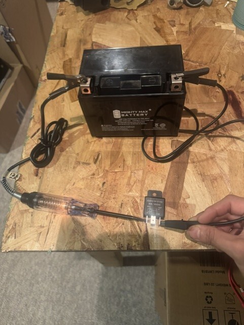 Question regarding video "Basic Electrical Review Part 1" under Basic Electrical Concepts folder. Time stamp 38mins - 39mins Paul covers using test light to energize control circuit of relay. I did the same test externally (as show in attached image) to practice using an incandescent test light to activate coil in a relay. But my test light bulb lit very dimly and coil field did work as relay did click. Why is that when Paul uses test light to energize coil in video, the light bulb in test light doesn't light up? isn't there current flowing thro the test light at that point in time when he is activating the relay coil?
test light correct use was created by CMat10
Last edit: 1 month 1 week ago by CMat10. Reason: forgot to add picture
Please Log in or Create an account to join the conversation.
- Chad
-

- Offline
- Moderator
-

- I am not a parts changer.
Less
More
- Posts: 2219
- Thank you received: 743
1 month 1 week ago - 1 month 1 week ago #93200
by Chad
"Knowledge is a weapon. Arm yourself, well, before going to do battle."
"Understanding a question is half an answer."
I have learned more by being wrong, than I have by being right.
Replied by Chad on topic test light correct use
The reason that the test light does not light is because of the resistance of the relay control coil. There is current flow, but the resistance of the control coil limits that current. There is enough current to activate the relay, but not enough to visibly illuminate the incandescent bulb.
This might not be a good analogy but, you can think of the relay control coil as being a "bad ground" that will not light a test-light.
This might not be a good analogy but, you can think of the relay control coil as being a "bad ground" that will not light a test-light.
"Knowledge is a weapon. Arm yourself, well, before going to do battle."
"Understanding a question is half an answer."
I have learned more by being wrong, than I have by being right.
Last edit: 1 month 1 week ago by Chad.
Please Log in or Create an account to join the conversation.
- CMat10
-
Topic Author
- Offline
- New Member
-
Less
More
- Posts: 18
- Thank you received: 1
1 month 1 week ago #93203
by CMat10
Replied by CMat10 on topic test light correct use
I see. Thanks. There are scenarios in which doing this same test the incandescent test light will light up though, right? Just really depends on the resistance of the relay coil being power side switched on.
Please Log in or Create an account to join the conversation.
- Chad
-
- Offline
- Moderator
-
- I am not a parts changer.
Less
More
- Posts: 2219
- Thank you received: 743
1 month 1 week ago - 1 month 1 week ago #93204
by Chad
"Knowledge is a weapon. Arm yourself, well, before going to do battle."
"Understanding a question is half an answer."
I have learned more by being wrong, than I have by being right.
Replied by Chad on topic test light correct use
You've got it.
Components wired in series share the source voltage. There is a voltage drop across each component, with the voltage drop depending on the resistance (or impedance) of each component.
In this scenario, the resistance of the test light is much lower than the resistance of the relay coil. Therefore, the test light has a much lower voltage drop across it and does not visibly illuminate. Most of the source voltage is dropped across the relay coil.
Now, suppose you were to do the same test on a fuel pump. The light might illuminate, but the fuel pump may not run. The test light limits the current and creates its own voltage drop, so there may not be enough voltage and current available for the pump to operate.
Do some reading on Kirchhoff's Voltage Law (KVL): the sum of all the voltage drops around a closed circuit is equal to the source voltage.
Also, check out Kirchhoff's Current Law (KCL). It explains the relationship between currents entering and leaving a junction in a circuit.
In this scenario, the resistance of the test light is much lower than the resistance of the relay coil. Therefore, the test light has a much lower voltage drop across it and does not visibly illuminate. Most of the source voltage is dropped across the relay coil.
Now, suppose you were to do the same test on a fuel pump. The light might illuminate, but the fuel pump may not run. The test light limits the current and creates its own voltage drop, so there may not be enough voltage and current available for the pump to operate.
Do some reading on Kirchhoff's Voltage Law (KVL): the sum of all the voltage drops around a closed circuit is equal to the source voltage.
Also, check out Kirchhoff's Current Law (KCL). It explains the relationship between currents entering and leaving a junction in a circuit.
"Knowledge is a weapon. Arm yourself, well, before going to do battle."
"Understanding a question is half an answer."
I have learned more by being wrong, than I have by being right.
Last edit: 1 month 1 week ago by Chad.
Please Log in or Create an account to join the conversation.
Time to create page: 0.321 seconds