Strange problem, PCM no communication - 2014 Dodge Ram 1500
- lmg866
-
 Topic Author
- Offline
- Senior Member
-

- Posts: 56
- Thank you received: 2
I am working on diagnosing a strange issue with a 2014 Dodge Ram 1500 5.7 6 speed automatic. The truck is a no crank no start. There is no check engine light on the dash with key on and I cannot communicate with the PCM. I can communicate with all of the other modules and have scoped the CAN bus, which appears to be operating normally. No codes are present in the other modules except for "lost communication with PCM." I purchased a second used PCM for the vehicle which behaves the same way when installed.
I have bench tested the two PCMs to see if they appear to be working properly. When powers and grounds of the PCMs are connected to a power supply on the bench, a change of state is observable at pins 7 and 80 (pin 7 is energized by the PCM; pin 80 is grounded by the PCM). These state changes energize the Powertrain Module Relay and the Auto Shutdown Relay, respectively, which feed power to other circuits of the PCM.
When I install the PCMs in the truck, I measure key on power at pins 96, 47, 23 of C1 of the PCM--however, the state change on pin 7 does not occur, and therefore power is not supplied to the Powertrain Module Relay, and the PCM (presumably) does not power up.
Because I was able to detect the state change on the bench, but not in the truck, I devised a system of bridging individual pins from the PCM to the PCM connector with breadboard leads. When I bridge only the powers, grounds, and CAN C lines, the state change is detectable, the PCM powers up, and communication is restored. However, when I again plug the PCM connectors directly into the PCM, connecting the rest of the pins, I get no communication.
What could be causing the PCMs to not change the state of pin 7 and not power up when the rest of the circuits are connected?
Please let me know if you have any questions about this situation, and thanks very much in advance for your thoughts.
Please Log in or Create an account to join the conversation.
- Chad
-

- Offline
- Moderator
-

- I am not a parts changer.
- Posts: 2180
- Thank you received: 732
"Knowledge is a weapon. Arm yourself, well, before going to do battle."
"Understanding a question is half an answer."
I have learned more by being wrong, than I have by being right.
")
Please Log in or Create an account to join the conversation.
- lmg866
-
Topic Author
- Offline
- Senior Member
-
- Posts: 56
- Thank you received: 2
On the PCM, C1 pins 69 and 93 are labeled 5V REF. C2 pin 87 is labeled 5V SPLY. I’ll check those tomorrow. Let me know if there are any others to add to my list, and I can post screenshots of the PCM diagram if helpful.
Please Log in or Create an account to join the conversation.
- lmg866
-
Topic Author
- Offline
- Senior Member
-
- Posts: 56
- Thank you received: 2
I should mention that I am able to make the PCM power up using the truck's power supplies with PCM C1 not plugged into the PCM by bridging individual pins between the PCM and C1 using breadboard leads. If all of the powers, grounds, and CAN lines into the PCM are connected, the MIL will illuminate with key on and the PCM will communicate with the scan tool.
My search for what circuit on PCM C1 could be bringing down the PCM comms continues.
Please Log in or Create an account to join the conversation.
- Chad
-
- Offline
- Moderator
-
- I am not a parts changer.
- Posts: 2180
- Thank you received: 732
This makes me suspicious of pin fitment. If the female terminals of the connector are too loose, it can cause connection issues. Are the male terminals of your breadboard leads larger/fatter than the PCM connector pin terminals? If the female terminals of the wiring harness are too loose, it will cause connection issues.I am able to make the PCM power up using the truck's power supplies with PCM C1 not plugged into the PCM by bridging individual pins between the PCM and C1 using breadboard leads.
"Knowledge is a weapon. Arm yourself, well, before going to do battle."
"Understanding a question is half an answer."
I have learned more by being wrong, than I have by being right.
Please Log in or Create an account to join the conversation.
- lmg866
-
Topic Author
- Offline
- Senior Member
-
- Posts: 56
- Thank you received: 2
Please Log in or Create an account to join the conversation.
- Chad
-
- Offline
- Moderator
-
- I am not a parts changer.
- Posts: 2180
- Thank you received: 732
Are there any other methods to verify pin fitment is or is not the issue?
It is not always easy to do so, but if you can open the PCM, you can test voltage drop from the wiring harness to the back side of the PCM connector, internal to the PCM.
"Knowledge is a weapon. Arm yourself, well, before going to do battle."
"Understanding a question is half an answer."
I have learned more by being wrong, than I have by being right.
Please Log in or Create an account to join the conversation.
- lmg866
-
Topic Author
- Offline
- Senior Member
-
- Posts: 56
- Thank you received: 2
I am considering for a next step trying to disconnect every component fed through C1 as well as looking for shorts to ground on each wire in order to isolate the problem to the PCM power supplies and pin fitment.
The other major set of components on C1 is the transmission solenoid pack. Would it be possible for a short here to activate circuit protection and prevent the PCM from powering up?
The above tests may be a waste of time as the PCM may not be attempting to power up any of those circuits. Is there any other circuit besides a shorted 5v ref that could be preventing the PCM from powering up?
Thanks for all of your ideas so far.
Luke
Please Log in or Create an account to join the conversation.
- lmg866
-
Topic Author
- Offline
- Senior Member
-
- Posts: 56
- Thank you received: 2
The next step is to depin the connector and install new female pins or crimp the existing pins to create more pin drag. Hopefully a post is forthcoming confirming the fix. And resources or tips on how to depin one of these Chrysler 96 pin PCM connectors would be appreciated--it's not immediately obvious how to do it.
Thanks,
Luke
Please Log in or Create an account to join the conversation.
- lmg866
-
Topic Author
- Offline
- Senior Member
-
- Posts: 56
- Thank you received: 2
I still have a couple of codes. P0882 (TCM Input Low), P0750 (LR Solenoid Circuit), and P0869 (Line Pressure High). The truck is in limp mode. After the codes are cleared, the truck usually seems to throw P0750 first, then P0869 and P0882. The resistance of the LR Solenoid Circuit is the same as the other shift solenoids, approximately 2 Ohms (tested at the PCM connector with multimeter). I have also monitored voltage with the scope at the TCM input wires at the PCM and found no dropouts--I measure 12v on those wires for the first several seconds after startup, after which the PCM cuts power to the PCM relay and so power at the TCM inputs is gone. Also, I have used an amp clamp to observe that the PCM appears to attempt to modulate the line pressure solenoid for the first few seconds of operation and then stops.
I am unfamiliar with this system and it seems as though these codes could be interrelated in a few ways, i.e. PCM throws line pressure code because a feature of limp mode is high line pressure? Or similarly, could the PCM throw TCM Input Low because the PCM has gone into limp mode? These don't seem possible from the descriptions of set conditions in AllData but maybe there are quirks I'm not aware of.
Please Log in or Create an account to join the conversation.
- Chad
-
- Offline
- Moderator
-
- I am not a parts changer.
- Posts: 2180
- Thank you received: 732
I would like to see the LR Solenoid Control Voltage and Current waveforms.I have also monitored voltage with the scope at the TCM input wires at the PCM and found no dropouts--I measure 12v on those wires for the first several seconds after startup
"Knowledge is a weapon. Arm yourself, well, before going to do battle."
"Understanding a question is half an answer."
I have learned more by being wrong, than I have by being right.
Please Log in or Create an account to join the conversation.
- lmg866
-
Topic Author
- Offline
- Senior Member
-
- Posts: 56
- Thank you received: 2
drive.google.com/file/d/1L2hJc2T4ohmw6bu...35v/view?usp=sharing
Please Log in or Create an account to join the conversation.
- lmg866
-
Topic Author
- Offline
- Senior Member
-
- Posts: 56
- Thank you received: 2
drive.google.com/file/d/1A1pcUzyzOgazcK5...x3R/view?usp=sharing
The pulses and spikes are much more pronounced on the MS Solenoid.
Please Log in or Create an account to join the conversation.
- Chad
-
- Offline
- Moderator
-
- I am not a parts changer.
- Posts: 2180
- Thank you received: 732

What version of Pico software are you using?
"Knowledge is a weapon. Arm yourself, well, before going to do battle."
"Understanding a question is half an answer."
I have learned more by being wrong, than I have by being right.
Please Log in or Create an account to join the conversation.
- lmg866
-
Topic Author
- Offline
- Senior Member
-
- Posts: 56
- Thank you received: 2
Please Log in or Create an account to join the conversation.
- lmg866
-
Topic Author
- Offline
- Senior Member
-
- Posts: 56
- Thank you received: 2
I have an ASTG book for an RFE transmission (68RFE, although this truck has a 65RFE) which says both LR and MS solenoids should be ON in Park. Neither appear to be drawing any significant current, however, even when there is voltage on the TCM Input wires.
Please Log in or Create an account to join the conversation.
- Chad
-
- Offline
- Moderator
-
- I am not a parts changer.
- Posts: 2180
- Thank you received: 732
let me know what you are interested in and I will try to post something representative.
The voltage waveform on the control wire should show battery voltage when the solenoid is not energized. When the PCM provides a ground and energizes the solenoid, voltage on the control wire should be pulled very close to 0 volts. When the PCM releases the ground and de-energizes the solenoid, the voltage one the control wire should spike to well over 30-40 volts, then return to battery voltage.
It would be good to see the current ramp, along with this voltage.
"Knowledge is a weapon. Arm yourself, well, before going to do battle."
"Understanding a question is half an answer."
I have learned more by being wrong, than I have by being right.
Please Log in or Create an account to join the conversation.
- lmg866
-
Topic Author
- Offline
- Senior Member
-
- Posts: 56
- Thank you received: 2
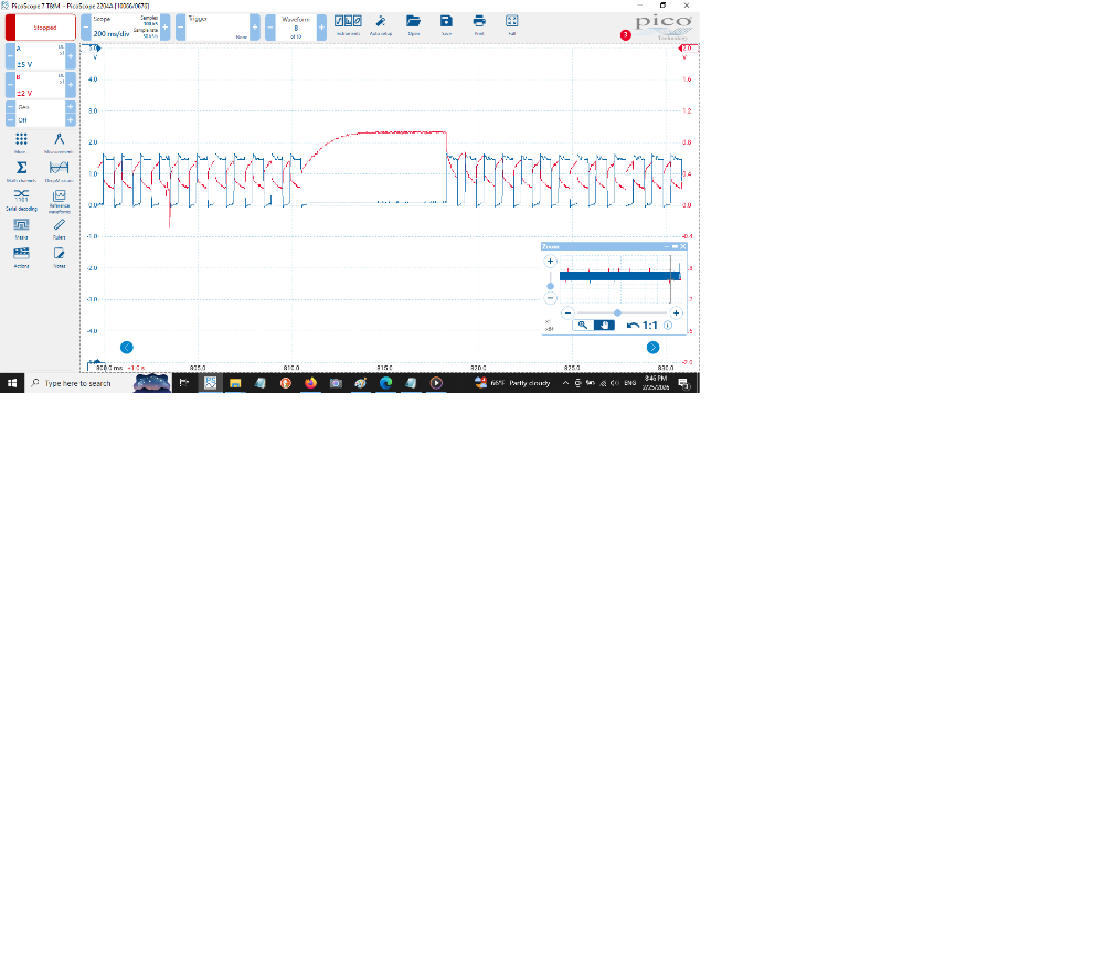
Hopefully you can see some of what you are looking for in the following. This is engine running, Red = current on LR Control, blue = voltage on LR control. The spike visible is the PCM cutting power to the TCM input wires and setting P0750.
Please Log in or Create an account to join the conversation.
- lmg866
-
Topic Author
- Offline
- Senior Member
-
- Posts: 56
- Thank you received: 2

Please Log in or Create an account to join the conversation.
- lmg866
-
Topic Author
- Offline
- Senior Member
-
- Posts: 56
- Thank you received: 2
Please Log in or Create an account to join the conversation.