2011 Chrysler 3.6 alternator charging circuit
- hobbsautomotiverepair
-
 Topic Author
- Offline
- Junior Member
-

- Posts: 37
- Thank you received: 7
So im having trouble with this van... and honestly im having serious doubts because i just ordered my bidirectional scan tool and it hasnt been delivered yet so everything so far has been done byway of fluke voltmeter and powerprobe. its a 2011 Chrysler town and country 3.6. customer called late stranded, her battery had run down, i went out had her towed, checked it that night and next morning and installed new battery and found that the alternator was not charging. so customer asked me to go ahead and just install the alternator because she needed the van...i installed as requested. still no charge. after brand new alternator and had them test prior to install and was good... after install of good alternator the alternator sense wire (red violet)wire is getting 9.34vdc but the battery side of alt is at 12.2vdc. and with test light on positive and i touch to the gen field control the (brown/grey)wire the test light illuminates constantly.... im so lost on this on... by all means this alternator should be full fielding.. so i took it down to my buddies shop with a snap on scanner and the pcm is ineed full fielding the alternator yet.. there is no charge at all. then today i foudn that if i unplug the alternator and test the voltage on the red/violet wire im getting 8.3VDC.... and when i test the same pin at the back of the alternator... i get no voltage drop.. its the same as the battery post and the battery positive of the alternator. but plug it back in and it goes back to the 8-9VDC. Can someone please explain to me how exactly this system should be tested or what i may be missing. i have identifix... but it doesnt give me a good pinout diagram of the pcm. im just at a loss at this point. i would appreciate all input and help. thanks so much everyone!!!
Chris
Please Log in or Create an account to join the conversation.
- Tyler
-
- Offline
- Moderator
-

- Full time HACK since 2012
- Posts: 6126
- Thank you received: 1542
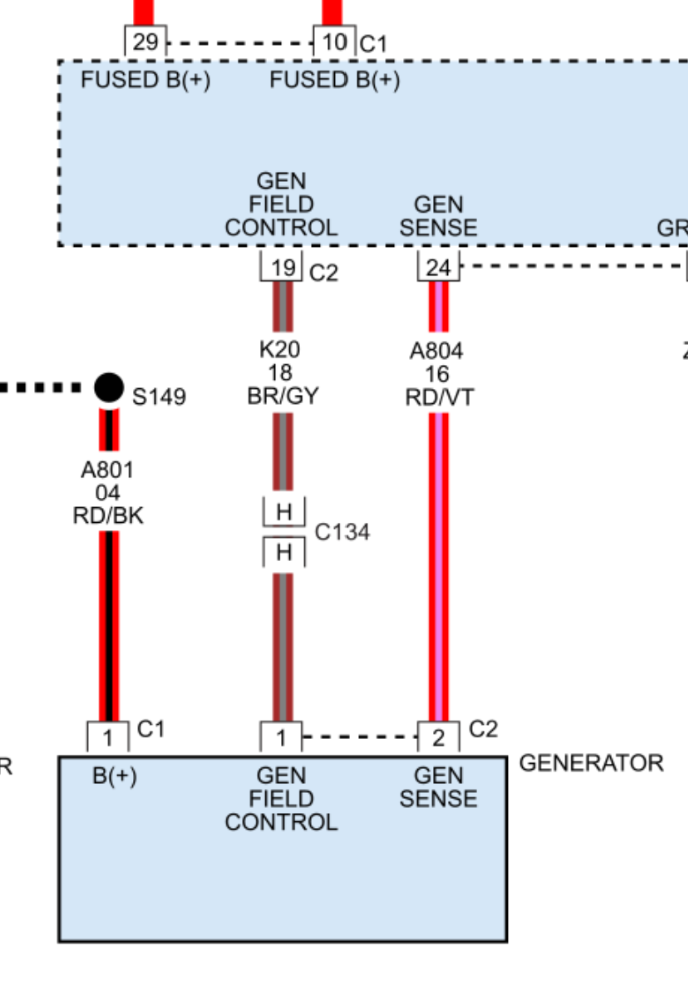
Sure! We can start out with the sense wire. This alternator setup uses what I've heard called a Kelvin sense circuit:Can someone please explain to me how exactly this system should be tested or what i may be missing.
autoprollc.com/wp-content/uploads/2016/1...ulletin_July_web.pdf
It's counterintuitive, because the voltage on the sense wire will NEVER match B+. Even when the system is charging normally. So, when you're seeing 9.34V on the sense wire with B+ at 12.2V, that's (weirdly) normal. I wouldn't sweat the sense circuit for now.
Second, the field control circuit. Again, this setup is different from most, in that the field control circuit uses voltage supplied by the PCM to control field current. It's a power side switched driver, instead of ground side switched.
Testing the field control circuit with the test light connected to B+ unfortunately won't tell you much, other than the test light finding a ground through the field winding in the alternator. You need to switch up and connect your test light to B- and touch the field circuit to get an idea of what's going on. Have the engine idling and the system not charging while you do this.
Alternately, you could disconnect the alternator and jump B+ directly to the field control pin on the alternator. If you're now charging at 15+V, you can be confident that the alternator is capable of output. Obviously, take care not to short B+ to ground while doing this, and don't leave it full fielded forever. Just long enough to see charging voltage.
Please Log in or Create an account to join the conversation.
- hobbsautomotiverepair
-
Topic Author
- Offline
- Junior Member
-
- Posts: 37
- Thank you received: 7
Please Log in or Create an account to join the conversation.
- Tyler
-
- Offline
- Moderator
-
- Full time HACK since 2012
- Posts: 6126
- Thank you received: 1542
=But anyways so I did the test you recommended and it is stalling the engine. So I did it almost like a “tapping” and I saw the battery voltage increase little by little but it definitely never went to 14-15vdc.
The engine stalling might be a good sign for the alternator? You can leave the jumper on there for more than a tap if you want. Five seconds would probably be enough.
Next step would be to verify the field control circuit between the alternator connector and the PCM.
I'm not very familiar with the newest Launch scanners out there. Is this the one?My launch431 pro5 pad7 will be in on Thursday. Do you have any knowledge of this scanner? It says it has j2534 capabilities which if I have to buy a pcm I thought I might have to have. But anyways again I appreciate your explanation and your advice! I’ll be on here a lot more often.
www.launchx431online.com/products/launch...riant=43826017796352
I really can't say if the tool itself will get a PCM swap done on this or not. My suspicion is not. Assuming a used PCM (and assuming the same software calibration), you'll need be able to do the 'PCM Replaced' function at a bare minimum. You'll also need the security PIN, which your new scan tool may or may not pull for you.
Search 'PROGRAMMING THE PCM' and 'MODULE/PROGRAMMING ORDER REPLACEMENT GUIDE' in Mitchell/SomeData/whoever you use for service info.
Please Log in or Create an account to join the conversation.
- hobbsautomotiverepair
-
Topic Author
- Offline
- Junior Member
-
- Posts: 37
- Thank you received: 7
Please Log in or Create an account to join the conversation.
- hobbsautomotiverepair
-
Topic Author
- Offline
- Junior Member
-
- Posts: 37
- Thank you received: 7
Please Log in or Create an account to join the conversation.
- hobbsautomotiverepair
-
Topic Author
- Offline
- Junior Member
-
- Posts: 37
- Thank you received: 7


Please Log in or Create an account to join the conversation.
- hobbsautomotiverepair
-
Topic Author
- Offline
- Junior Member
-
- Posts: 37
- Thank you received: 7


Please Log in or Create an account to join the conversation.
- Tyler
-
- Offline
- Moderator
-
- Full time HACK since 2012
- Posts: 6126
- Thank you received: 1542
I feel as though you’re taking the time to help me and I’m now missing your much needed and appreciated feedback.
Was not my intention to leave you hanging, and I'm sorry if that's caused you any headaches. Helping out here on the forums is a part time gig for me, so I catch up and help out where I can.
So when I connect the field control wire to battery voltage can I do this while it is connected to the pigtail on the alternator? Or ONLY WHILE THE PIGTAIL IS UNPLUGGED?
Technically, either way. The reason I suggested unplugging the alternator was to eliminate the possibility harness damage if the field control circuit it shorted to ground somewhere. Not very likely, but still possible. Also, the field circuit in the alternator may draw several amps while full fielded, which can cause damage to some smaller backprobes/T-pins.
Please keep in mind the alternator has tested good and I’ve swapped it out now twice testing it first prior to installing it. All wiring from pin to pin has good integrity and continuity. But still no charge.
If you're confident in wiring integrity, and you've shown that the alternator can charge, then you're down to a PCM.
Have you tried looking for the aforementioned 'PCM Replaced' function in your new scan tool? That would be a good starting point to see if you're capable of making a replacement module work.
You could also consider a repair service, like Automotive Circuit Solutions:
www.automotivecircuitsolutions.com/colle...puter-repair-service
Please Log in or Create an account to join the conversation.
- hobbsautomotiverepair
-
Topic Author
- Offline
- Junior Member
-
- Posts: 37
- Thank you received: 7
Please Log in or Create an account to join the conversation.
- Tyler
-
- Offline
- Moderator
-
- Full time HACK since 2012
- Posts: 6126
- Thank you received: 1542
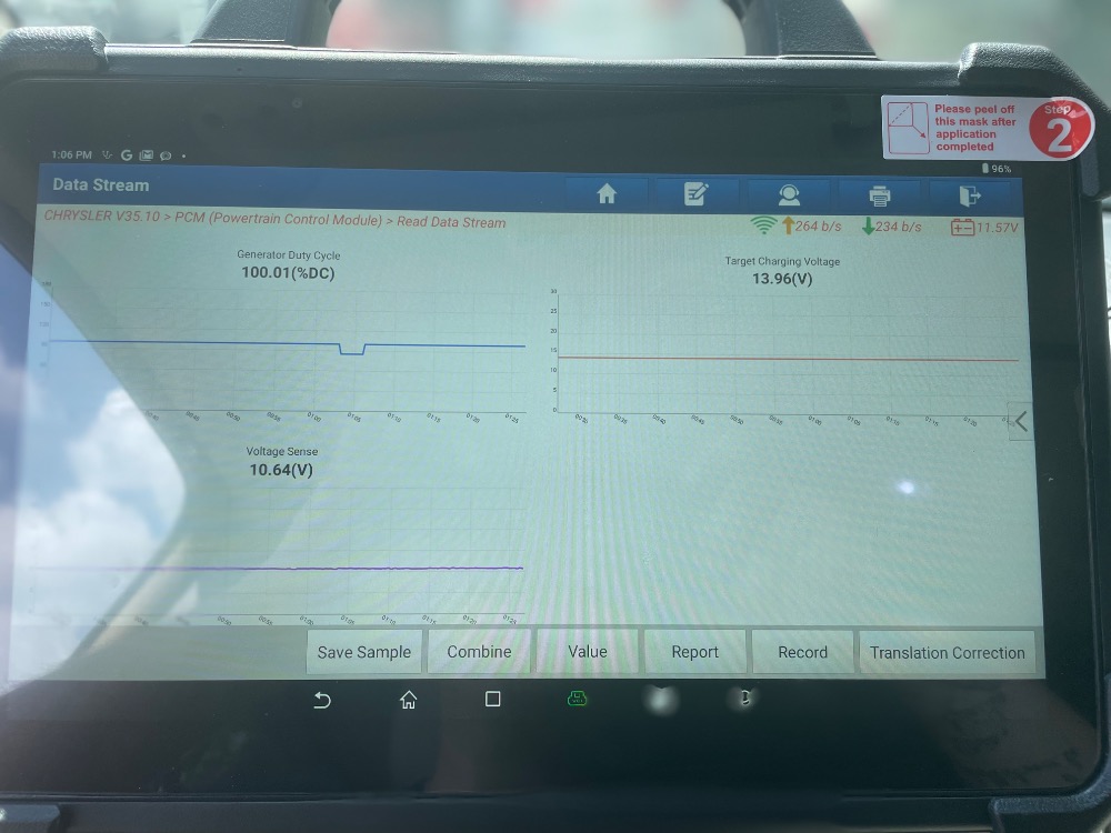
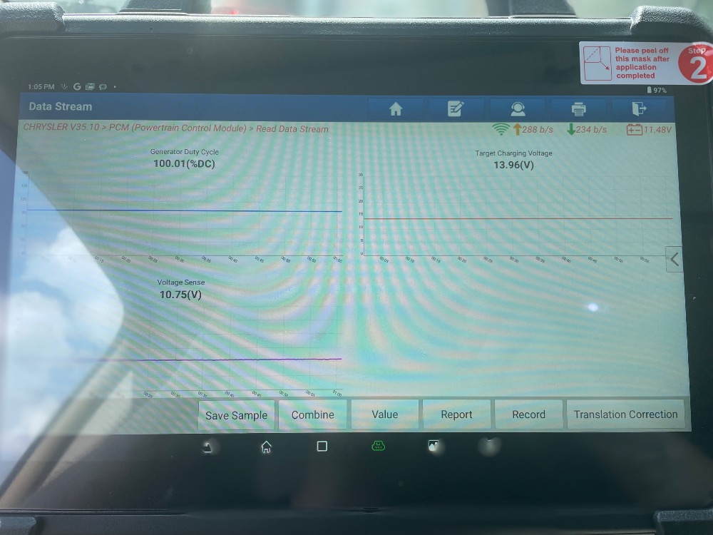
and heres my thoughts on this. My scan tool is reading desired voltage at 13.96vdc. and its reading generator field 100.1%. yet im still not charging. so by all means to me it looks as though the pcm is good... is it possible that its still not?
Absolutely, the PCM is still suspect.
The 100% field command PID shows that the PCM wants the alternator to charge. But that doesn't mean the PCM has the physical means to make it happen. Remember, the PCM must be able to supply current to the alternator on the field control circuit to get the alternator to charge. That field command PID will read 100% all day long even if the high side driver in the PCM is completely smoked.
That's why the test light test I suggested is important. Incandescent test light to B-, field command at 100%. The PCM should be able to light the bulb. If it can't, then either there's a wiring problem (which you've tested for), or there's a PCM problem.
so, I do think that this pigtail is a problem. so i bought and am about to install a new pigtail to eliminate it from the situation.
Was there something about the pigtail that made you suspect it? Honest question. When you were doing resistance testing, did you include the female pin of the pigtail in the test?
Please Log in or Create an account to join the conversation.
- hobbsautomotiverepair
-
Topic Author
- Offline
- Junior Member
-
- Posts: 37
- Thank you received: 7
Please Log in or Create an account to join the conversation.
- Tyler
-
- Offline
- Moderator
-
- Full time HACK since 2012
- Posts: 6126
- Thank you received: 1542
well... to be honest with you.. its my nature to constantly want to be 100% positive of myself prior to making a call. and on this one i honestly wasnt completely sure of myself.
I completely understand. We're all about having that 100% confidence going into repairs like this.
The Pigtail itself was just loose, and it was suspect to me. however had good continuity from pin to pin so i wasnt concerned until i had time to think about this for two weeks lol.
Gotcha.
i got the PCM from all computer resources and it says its plug and play.
This is the place? store.allcomputerresources.com/
We'd love to know how the replacement goes, if you don't mind following up?
they mention something about the Torque converter clutch solenoid being shorted being the number one cause of pcm failure and this being often overlooked.
That's interesting. I do know that the solenoids in the 62TE transmission like to short pretty often. But I've never seen one of these vans that had a shorted transmission solenoid AND a charging system problem, or vice versa.
something had to make this pcm go bad.. so what, in your experience makes the pcms Drivers fail?
Based on no engineering knowledge and just my anecdotal experience?
Add to that, I find that weak batteries speed the failure along. Specifically, batteries with high recharge current.
In short, the battery fails internally in such a way that it becomes a current sink. Current goes in, but the battery doesn't actually recharge. That ends up adding a ton of load to the charging system. The really bad examples I've seen added 50-60A of load all by themselves. Add that on top of normal vehicle loads, plus the front and rear A/C in the summer, and pretty soon the alternator is spending its whole life full fielded just trying to keep up.
On most vehicles with internally regulated and/or 'smart' charging systems, that just ends with a failed alternator. No big deal. But with this setup, you're also stressing the PCM driver.
Please Log in or Create an account to join the conversation.
- hobbsautomotiverepair
-
Topic Author
- Offline
- Junior Member
-
- Posts: 37
- Thank you received: 7
As far as the Repair on the 2011 Chrysler T&C 3.6... The PCM install went flawlessly. The website you listed from allcomputerresources was correct by the way. and it was plug and play. i did not need to do anything to it with my scan tool other than ETC Learn and i test drove it afterwards. I cant thank you enough for your wisdom and your continued support and responses in this brother! Wish i had someone like you to call haha. but VEHICLE IS VERIFIED REPAIRED. ALTERNATOR IS CHARGING AND PULSE WIDTH MODULATING AS DESCRIBED. I agree with you about the engineering about the load on the pcm itself..there are alot of components for this van to handle and it seems to be 80% fielded all the time with the a/c on, and thats just the front blower motor. i can guarantee you are correct in your statement. and again, thank you so much! my customer is filled with joy. and so am I to see her happy and know her vehicle is reliable again.
Chris
Please Log in or Create an account to join the conversation.
- Tyler
-
- Offline
- Moderator
-
- Full time HACK since 2012
- Posts: 6126
- Thank you received: 1542
Glad to hear this one is fixed and down the road.
Please Log in or Create an account to join the conversation.
- hobbsautomotiverepair
-
Topic Author
- Offline
- Junior Member
-
- Posts: 37
- Thank you received: 7
Please Log in or Create an account to join the conversation.
- Tyler
-
- Offline
- Moderator
-
- Full time HACK since 2012
- Posts: 6126
- Thank you received: 1542
You CAN run the transmission quick learn on your scan tool. However, I'd caution your customer that running relearn procedures on used transmissions always carries a risk.
Check the fluid level/condition while you're there. Do you have the trans dipstick?
Of course, the bigger problem is history. You don't really know how it shifted before your testing/repairs, because you're likely not going to test drive a van with a charging system problem.
Please Log in or Create an account to join the conversation.
- hobbsautomotiverepair
-
Topic Author
- Offline
- Junior Member
-
- Posts: 37
- Thank you received: 7
chris
Please Log in or Create an account to join the conversation.
- Tyler
-
- Offline
- Moderator
-
- Full time HACK since 2012
- Posts: 6126
- Thank you received: 1542
say i have this same situation and i go into my scan tool and preform a quick learn on the transmission... can you explain to me what exactly this step does.
chris
Chris, I can't really explain how automatic transmissions do anything at all.
I couldn't find anything in service information that spells out exactly what's going on with the transmission quick learn. But I'm guessing that the quick learn is trying to get the Clutch Volume Index values in the ballpark before a test drive. Minimize clutch slip, harsh engagement, ect.
If you have a vehicle you're willing to FAFO with, you can clear the trans adapts, run the quick learn and test drive it. The CVI's will start at a base set of values and update from there. You can check the CVI's at each step and watch who's changing and how much.
Please Log in or Create an account to join the conversation.