2010 Dodge Charger 5.7 Alternator Waveform
- blazer64
-
 Topic Author
- Offline
- New Member
-

- Posts: 7
- Thank you received: 0
I think a little background on the car would help here. I have had this issue for as long as I have owned the car for about 2 years now. It seems to have a little random misfire/rough running noticeable when the car is at idle. The roughness car really be felt when the car is in park and you rev the engine slightly. No codes have ever been registered relating to the issue (only some I create when troubleshooting). The car also seems very sluggish and just doesn't feel right. I can make the car drive a bit better by resetting the ecu but once the car is driven and the car learns the fuel trims it goes back to being sluggish. I feel like I have checked every system on the car and never find a real problem.
Onto my main question. I was looking at alternator ripple on an old analog 60 MHz oscilloscope and the waveform I saw was very weird. I tried to take a picture with my phone but because the oscilloscope is an old CRT type I could not get a clear picture. I had 400mv peak to peak ripple at idle which seems a bit high but I cannot say for sure that it is definitely causing a problem or not. I dont have any issues starting the car so the alternator in its current state is charging the battery.
The waveform itself was also very peculiar in that it did not look like a series of nice humps in some example waveforms I have seem but rather very spiky with some humps like I would expect sprinkled in. I did disconnect the alternator field winding connector and drove the car, It did run very well and the issues seemed to disappear but I have been fooled before. I really dont want to throw more parts at the car without some evidence. My theory is that since the computer uses system voltage in its base fuel calculations the amount of fuel being delivered is always changing making the car run rough

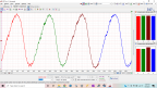
Using the very best graphics design program to date (Microsoft Paint) I have drawn to the best of my ability what I saw on the scope. The section labeled "A" is very spiky and looks very noisy. Section "B" shows the nice humps you see when you lookup a "good" alternator waveforms but with a bit more amplitude. Section "C" looks like A and has the same characteristics. This pattern repeats over and over again.
So i put it to you, the good people on the Scanner Danner forum. What are your thoughts on what I observed. I would love to hear what you all think.
Thanks,
Mitchell
Please Log in or Create an account to join the conversation.
- Dylan
-

- Offline
- Moderator
-

- Belgium, Europe
- Posts: 1462
- Thank you received: 327
I can make the car drive a bit better by resetting the ecu but once the car is driven and the car learns the fuel trims it goes back to being sluggish.
Can you tell us what your fuel trims are? How do the O2's react. Some feedback values could help.
Onto my main question. I was looking at alternator ripple on an old analog 60 MHz oscilloscope and the waveform I saw was very weird. I tried to take a picture with my phone but because the oscilloscope is an old CRT type I could not get a clear picture. I had 400mv peak to peak ripple at idle which seems a bit high but I cannot say for sure that it is definitely causing a problem or not.
Hmmm 400mV peak to peak is not that high.
Weird picture though. Just asking but have you tried that scope on another vehicle?
Please Log in or Create an account to join the conversation.
- blazer64
-
Topic Author
- Offline
- New Member
-
- Posts: 7
- Thank you received: 0
Can you tell us what your fuel trims are? How do the O2's react. Some feedback values could help.
Values at idle are about -6% on both banks. revving the motor i can make the total fuel trims reach up to about -15% and then the system corrects again. This tells me the o2's can control the fuel trim.
I have replaced the o2's with oem brand (NTK) sensors with no change.
Hmmm 400mV peak to peak is not that high.
Weird picture though. Just asking but have you tried that scope on another vehicle
I have not tried it on another vehicle however probing other signals works with the scope and behaves how I expect so I have no reason to suspect that the scope is malfunctioning in some way.
I think I need to remeasure the ripple while someone rev's the engine since this is when the problem is the worst. The car is fly by wire so I cannot rev the engine from the engine bay unfortunately.
Please Log in or Create an account to join the conversation.
- cheryl hartkorn
-
- Offline
- Platinum Member
-

- Posts: 694
- Thank you received: 130
Please Log in or Create an account to join the conversation.
- Andy.MacFadyen
-

- Offline
- Moderator
-
- Posts: 3357
- Thank you received: 1037
If it wasn't for the negative fuel trim at idle I would think vacuum leak.
" We're trying to plug a hole in the universe, what are you doing ?. "
(Walter Bishop Fringe TV show)
Please Log in or Create an account to join the conversation.
- Tyler
-
- Offline
- Moderator
-
- Full time HACK since 2012
- Posts: 6115
- Thank you received: 1539
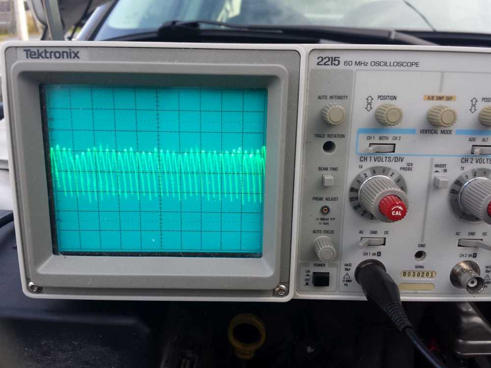
Just as an example, this is a capture I took off a Honda with a failing alternator:
This one had a failed diode and low output. Note the 20ms screen time - that's around what you'll need to see detail in your alternator ripple waveform.
If you wanted to test your theory about the alternator causing the rough running, you could try unplugging the field control connector at the alternator
") It'll stop charging, of course, but it'd also eliminate any ripple in the system.
It'll stop charging, of course, but it'd also eliminate any ripple in the system. Please Log in or Create an account to join the conversation.
- Andy.MacFadyen
-
- Offline
- Moderator
-
- Posts: 3357
- Thank you received: 1037
This is a good (at least working with no problems) voltage waveform from a high mileage late 1990s Denso atlernator. The scope is set to AC volts.

" We're trying to plug a hole in the universe, what are you doing ?. "
(Walter Bishop Fringe TV show)
Please Log in or Create an account to join the conversation.
- blazer64
-
Topic Author
- Offline
- New Member
-
- Posts: 7
- Thank you received: 0
Tyler wrote: Man, that's a pretty good picture for using Paint! I've seen similar alternator ripple waveforms when I had the time scale set too long, resulting in scope aliasing. Do you recall what the time scale was during your testing?
Just as an example, this is a capture I took off a Honda with a failing alternator:
This one had a failed diode and low output. Note the 20ms screen time - that's around what you'll need to see detail in your alternator ripple waveform.
If you wanted to test your theory about the alternator causing the rough running, you could try unplugging the field control connector at the alternator
I would agree with you about the scope settings however this pattern shows up in all time scales and the fact that it seems like a good pattern (minus the amplitude) is in their some of the time. I will definitely hook the scope up again and test some more this weekend. I cannot recall what time base i was using i just adjusted the time base until I could get a good picture of all the action.
Thanks for all the replies. Its definitely got me thinking. I will post an update hopefully this weekend with perhaps a pic of the waveform if I can get the camera to pick it up.
Please Log in or Create an account to join the conversation.
- blazer64
-
Topic Author
- Offline
- New Member
-
- Posts: 7
- Thank you received: 0
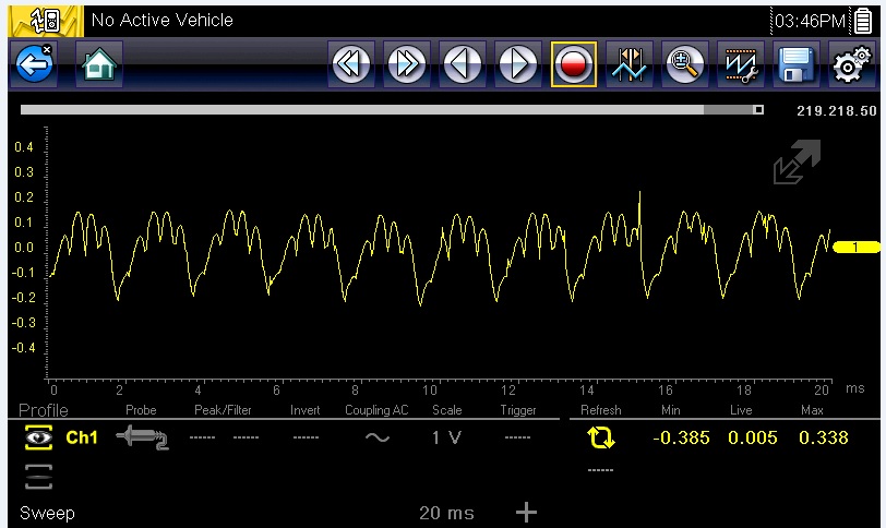
This is the best picture i could get with a .2 ms per division time scale and a .2 volt per division voltage scale. This picture does not look too bad apart from the amplitude but like was mentioned that is normal.
When I turn on the blower motor, rear window defrost, headlights, and wipers the waveform gets noisy and spiky but the amplititude does not change so my only assumption is that something I am turning on is introducing the noise which is why I am getting the pattern I was getting.
From these tests it looks like the alternator is OK. The amplitude had me puzzled but the battery for this car is in the trunk and with is being so far away maybe the battery cannot smooth the waveform as much as if it was in the engine bay.
As for my original problem I took a good long drive and observed the fuel trims. When driving the long terms are right about 0 and the short terms switch around 0 like I would expect. Only when I am in park when the engine is under little to no load do the fuel trims act up when I have the engine revved. It really sounds like a vacuum leak from the symptoms but I have been through the intake 3-4 times looking for a leak and even rigged up a way to get smoke into the intake and no leaks! I had suspect the brake booster since it has a check valve but it does hold a vacuum for a good time after the car is shut off. I dont know where to look next!
Please Log in or Create an account to join the conversation.
- Noah
-
- Away
- Moderator
-
- Give code definitions with numbers!
- Posts: 5008
- Thank you received: 1116
Or introduce smoke into the booster itself.
This one ended up being a booster
"Ground cannot be checked with a 10mm socket"
Please Log in or Create an account to join the conversation.
- blazer64
-
Topic Author
- Offline
- New Member
-
- Posts: 7
- Thank you received: 0
Please Log in or Create an account to join the conversation.
- Noah
-
- Away
- Moderator
-
- Give code definitions with numbers!
- Posts: 5008
- Thank you received: 1116
I like the idea of pinching off the booster hose too, that should do the trick.
"Ground cannot be checked with a 10mm socket"
Please Log in or Create an account to join the conversation.
- blazer64
-
Topic Author
- Offline
- New Member
-
- Posts: 7
- Thank you received: 0
A Scan Tool may be used to learn electrical parameters. Go to the Miscellaneous menu, and then select ETC Relearn. If the relearn is not preformed, a Diagnostic Trouble Code (DTC) will be set. If necessary, use a scan tool to erase any Diagnostic Trouble Codes (DTC's) from PCM.
The throttle body and gas pedal have been replaced (I know.... I should have tested. We will call that a "learning experience") and no relearn has been done. No codes have ever been thrown so what ever values may be stored in memory are not far off enough to cause a DTC to be triggered but might be off enough to cause low load issues.
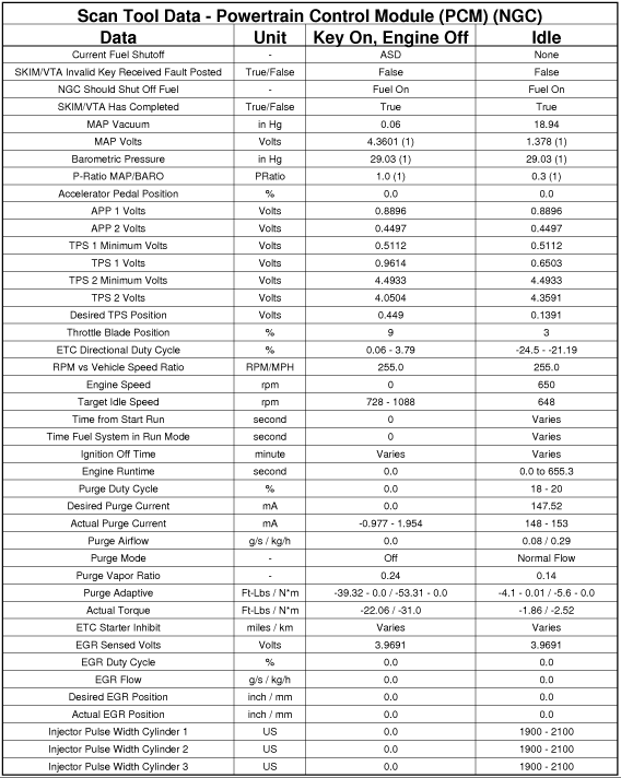
Here's a table i found on alldata showing that minimum and maximum TPS values are stored I just dont know when if they update over time or are stored for life. The TPS is built into the throttle body so its possible that they may be out just enough. Might be barking up the wrong tree again though.
The throttle body is made by siemens/VDO which was probably taken from Mercedes and is used in VW's\Audi's. There is much more info available for the German cars and from what I can find a relearn must be done after throttle body replacement and even cleaning.
Please Log in or Create an account to join the conversation.
- Noah
-
- Away
- Moderator
-
- Give code definitions with numbers!
- Posts: 5008
- Thank you received: 1116
I figured there would have been a separate heading for it, but like you said, it's at the end of the installation procedure.
Do you have an enhanced scan tool? I can't say for certain, but I imagine a Snap-On or OTC would have the procedure.
Alldata also says a DTC will set if the relearn isn't performed, but you say there is no ETC fault code, or just no CEL?
I've never changed one, so I can't say for sure, but I would encourage a relearn if you have the capability.
"Ground cannot be checked with a 10mm socket"
Please Log in or Create an account to join the conversation.
- blazer64
-
Topic Author
- Offline
- New Member
-
- Posts: 7
- Thank you received: 0
Thanks for the reply's guys!
Please Log in or Create an account to join the conversation.