Help us help you. By posting the year, make, model and engine near the beginning of your help request, followed by the symptoms (no start, high idle, misfire etc.) Along with any prevalent Diagnostic Trouble Codes, aka DTCs, other forum members will be able to help you get to a solution more quickly and easily!
Crank no start
- Ttleader23
-
 Topic Author
- Offline
- New Member
-

Less
More
- Posts: 5
- Thank you received: 0
10 months 4 weeks ago #89971
by Ttleader23
Crank no start was created by Ttleader23
Hello
Mazda 2014 2.2D sky activ Crank no start, no crankshaft rpm signal and no injector pulse
I was reading an earlier post by Gamur17 on the test procedure for signal issues and need help to interpret my findings
With a test light to ground, CKP sensor unplugged, scope on signal at PCM, and watching the rpm PID on the scanner.
Repeatedly tap the signal wire, can you make a square wave, and does the PCM produce an rpm?
I have 5v ref, 5v signal, and a good earth (3 wire hall effect sensor)
The results of this test are that I can produce a square wave signal but still have no RPM signal at the scan tool
Where should I begin to look and why this is ?
Any suggestions would be helpful
The reluctor wheel is correctly aligned and all three of my crankshaft sensors work in my other mazda 2.2d
Please Log in or Create an account to join the conversation.
- Chad
-

- Offline
- Moderator
-

- I am not a parts changer.
Less
More
- Posts: 2173
- Thank you received: 727
10 months 3 weeks ago - 10 months 3 weeks ago #89978
by Chad
"Knowledge is a weapon. Arm yourself, well, before going to do battle."
"Understanding a question is half an answer."
I have learned more by being wrong, than I have by being right.")
Replied by Chad on topic Crank no start
That means that the signal wire is good. Leave your scope connected to the signal wire at the pcm connector. Reconnect the crank sensor and crank the engine. Are you getting a square wave? If so, it's not looking good for your PCM.
If you are getting a square wave from the crank sensor to the PCM, post a screen shot of the square wave. Be sure that the voltage scale is visible and easy to read.
If you are getting a square wave from the crank sensor to the PCM, post a screen shot of the square wave. Be sure that the voltage scale is visible and easy to read.
"Knowledge is a weapon. Arm yourself, well, before going to do battle."
"Understanding a question is half an answer."
I have learned more by being wrong, than I have by being right.
Last edit: 10 months 3 weeks ago by Chad.
Please Log in or Create an account to join the conversation.
- Ttleader23
-
Topic Author
- Offline
- New Member
-
Less
More
- Posts: 5
- Thank you received: 0
10 months 3 weeks ago #89993
by Ttleader23
Replied by Ttleader23 on topic Crank no start
Thanks for your reply Chad
I have completed the suggested test. scope connected to the signal wire, crank sensor installed and connected. (Camshaft sensor still disconnected)
I have a Powerprobe with a scope but as its self ranging I cannot adjust the wave.
I've taken a picture of the video so information is limited but I can say that it compares with my working mazda 2.2d
Further to this I have tested the voltage and ohms of the HS can at the pcm and beyond.
At the ABS module, instrument cluster, FBCM, SSU, fuse box connection to emmissions harnes and all voltages appear correct
Results of the back probe test of the pcm HS can are, can H 2.7v can L 5v
Results of a wire "pin prick" to the HS can wires next to the pcm can H 2.7v can L 2.3v
Results of ohm test across the HS can H&L pcm pins with the plug disconnected 120ohms
I have checked the back probe figure several times as I don't understand how that can be?
Attachment not found
Please Log in or Create an account to join the conversation.
- Ttleader23
-
Topic Author
- Offline
- New Member
-
Less
More
- Posts: 5
- Thank you received: 0
10 months 3 weeks ago - 10 months 3 weeks ago #90001
by Ttleader23
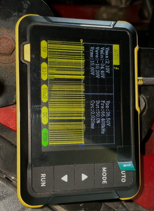
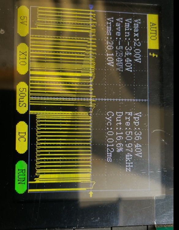
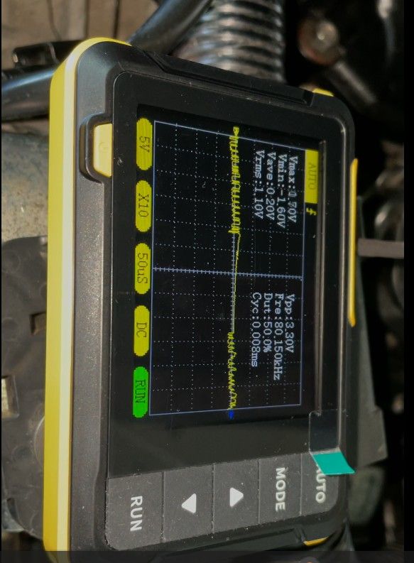
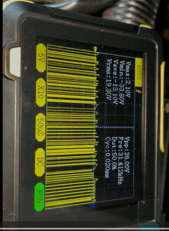
Further to my earlier post I have borrowed a small scope and have measured the HS can at various points. Unfortunatly I am unable to measure the running car at the pcm
The HS can at the pcm on the non running car has lower activity when connected to the pcm. When disconnected the activity increases to a level seen at other parts of the HS can.
The voltage reading may give a clue to what could be wrong.I'm sure this is telling me something however I'm not familiar enough with scopes to interpret the info, can you help?
Whilst there is communication with the pcm and all other modules on the scan tool the rpm signal doesn't reach it. The immobiliser says it's off. There are no DTC'sScope setting were kept the same. pictures added
Replied by Ttleader23 on topic Crank no start
Further to my earlier post I have borrowed a small scope and have measured the HS can at various points. Unfortunatly I am unable to measure the running car at the pcm
The HS can at the pcm on the non running car has lower activity when connected to the pcm. When disconnected the activity increases to a level seen at other parts of the HS can.
The voltage reading may give a clue to what could be wrong.I'm sure this is telling me something however I'm not familiar enough with scopes to interpret the info, can you help?
Whilst there is communication with the pcm and all other modules on the scan tool the rpm signal doesn't reach it. The immobiliser says it's off. There are no DTC'sScope setting were kept the same. pictures added
Last edit: 10 months 3 weeks ago by Ttleader23.
Please Log in or Create an account to join the conversation.
Time to create page: 0.299 seconds