2013 Ford F-150 5.0 - Crank no start. Good CKP signal, no tach output.
- lmg866
-
 Topic Author
- Offline
- Junior Member
-

- Posts: 35
- Thank you received: 1
Good thought to test the signals without the computer on. I repeated the tests cranking the starter by jumping the starter relay contacts, with the connector connected and disconnected at the PCM. Same results as with the computer on.
The red trace is CKP-, if it makes a difference. Green wire in the diagram.
The only condition that makes the waveform show up on the red trace is if both scope channels 1 and 2 negative leads are disconnected from battery negative and left dangling. Connecting one or the other or both scope negative leads to battery negative results in the red trace waveform flatlining.
bills4065:
Could you describe specifically what about the scope capture looks like a failing sensor?
I am inclined to absolutely positively condemn the sensor if that is the problem, as the CKP on these is located on the back of the engine squeezed underneath the firewall. They can also become extremely stuck, requiring transmission removal to get them out, which looks like it may be the case with this one....
Please Log in or Create an account to join the conversation.
- ferris48
-

- Offline
- Premium Member
-

- Posts: 129
- Thank you received: 47
The red trace is slightly elevated above zero volts and there's a diminished crank signal in there that aligns too well with the blue signal to be voltage drops from starter draw. That would indicate that the PCM is sending out some DC voltage but the CKP sensor is failing at its job to create a signal. bills4065 may be right on a bad ckp call, but I would do some additional checks just to be extra sure like check the 2 wires from where you unplugged the computer for a short to ground, ohm check sensor resistance for acceptable range which is 250 - 1,100 ohms, maybe reseat the ckp connector if anything looks off. Perhaps run a test light voltage though this sensor and scope it on the other wire, give the wiring a shake and tumble to make sure the scope trace remains steady. If those tests pass and there's still no signal on both wires, then yes I think it's time for crank sensor replacement.Could you describe specifically what about the scope capture looks like a failing sensor?
Please Log in or Create an account to join the conversation.
- lmg866
-
Topic Author
- Offline
- Junior Member
-
- Posts: 35
- Thank you received: 1
Please Log in or Create an account to join the conversation.
- ferris48
-
- Offline
- Premium Member
-
- Posts: 129
- Thank you received: 47
Please Log in or Create an account to join the conversation.
- lmg866
-
Topic Author
- Offline
- Junior Member
-
- Posts: 35
- Thank you received: 1
Test light connected to battery positive and CKP+. Scope connected to CKP- and battery negative. Correct?
Please Log in or Create an account to join the conversation.
- ferris48
-
- Offline
- Premium Member
-
- Posts: 129
- Thank you received: 47
Please Log in or Create an account to join the conversation.
- lmg866
-
Topic Author
- Offline
- Junior Member
-
- Posts: 35
- Thank you received: 1
I tested the circuit for short to ground and found 3.8 MOhms. Spec is greater than 10 KOhms.
I disconnected each wire at the sensor and tested it to ground. Once disconnected from the sensor, the resistance went to Open. Therefore, the 3.8 MOhms to ground must be in the sensor.
CKP+ to CKP- resistance is 700 ohms. In spec.
I attached the positive scope leads to each pin of the CKP sensor with the wiring detached from the sensor, and attached both scope negatives to battery negative. The waveform is the same as when testing at the PCM connector.
I do not think the wiring is to blame.
I have another sensor that I could test against the old one. I just had the thought to test it in exactly the same way as the old one: scope negative leads to battery negative. However, I seem to have badly misplaced the spare sensor, so that will have to wait until I stumble upon it again, hopefully later today.
Again, I am only hesitant to replace the sensor at this point because it will probably require transmission removal to dislodge it. My continued appreciation for the coaching!
Please Log in or Create an account to join the conversation.
- bills4065
-
- Offline
- Premium Member
-
- Posts: 136
- Thank you received: 16
Please Log in or Create an account to join the conversation.
- lmg866
-
Topic Author
- Offline
- Junior Member
-
- Posts: 35
- Thank you received: 1
Are you saying that you think the CKP signal is good? Can you say more about what you are looking at that prompted this change in thinking?I reread your initial hookup of your scope. You have a 1 volt vrs signal getting to the computer. Paul's book calls for minimum +/- 500 millivolts. Do you have any previous history of what has gone on with this truck?
Please Log in or Create an account to join the conversation.
- bills4065
-
- Offline
- Premium Member
-
- Posts: 136
- Thank you received: 16
Please Log in or Create an account to join the conversation.
- ferris48
-
- Offline
- Premium Member
-
- Posts: 129
- Thank you received: 47
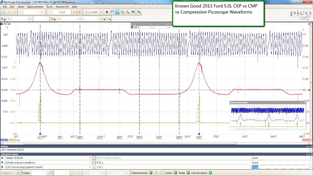
Here are some known good waveforms I found from diag.net but they're at 600-700 RPM with peak to peak voltage 4V roughly. They're kinda useless for comparison to your cranking waveform, except to show off the 2V bias from the computer. That would mean the scope was referencing battery negative for the capture and there was 2V bias voltage on this wire from the computer. Also note the rising edge for the crank index for the missing tooth. This also would mean that both captures were scoping the same wire, either ckp- or ckp+ . My money is on the scope was on ckp+
And then there is this YouTube video showing a cranking waveform:
Here is the screenshot from that video. The annotation is not mine.
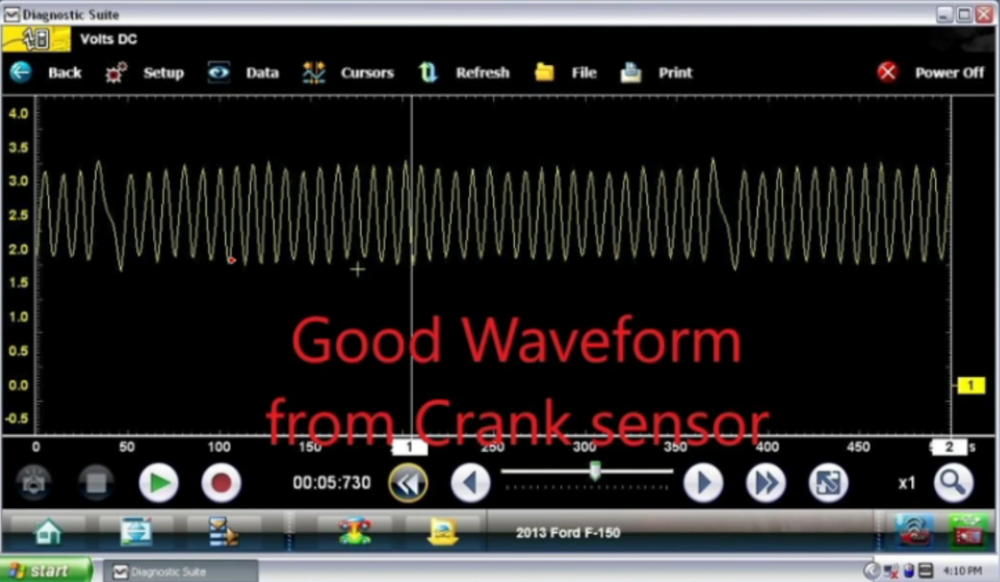
The bias voltage is at 2.5V from the computer and 184 RPM and peak to peak voltage is 1V -1.5V roughly. The crank index is a falling edge. This means he was on the other ckp wire, whereas the 2 captures from diag.net were on the same wire. My money is on the scope was on ckp- that would explain why the crank index is a falling edge in this YouTube video. And scope negative is on battery negative. If his scope leads were switched around, then the bias voltage would be at negative 2.5V.
I wish I had another known good cranking waveform to analyze to be certain.
You bias voltage is way too low and I calculate your cranking RPM to be 171 RPM, roughly in line with the YouTube video, and your sensor is making peak to peak voltage of 3V. The YouTube video on a known good showed 1v-1.5V. Your sensor shows a flatline on the other wire which should not be. I think you wrote that the flatline signal was on ckp- wire which is concerning because your ckp+ is showing a falling edge for the crank index. I believe it should be the rising edge, but I could be wrong.
Right now the signs are pointing at this crank sensor.
But I want to eliminate some variables.
Can you do a single channel scope capture so I can rule out a faulty scope? Scope the ckp- , the flatline one, with your scope at battery negative, then disconnect the scope and move on to the ckp+ . Single channel only. Is ckp- still flatline? PCM connected, PCM disconnected make any difference?
Is it worth swapping the ckp- and ckp+ wires around. Yes this will involve mutilating the wires but it's worth experimenting. If go you this route, what is the voltage coming out of the computer on those 2 wires with the ckp removed and cranking?
I mentioned earlier in the thread about putting 2.5v from a variable resistor from the 5v ref circuit into the ckp circuit. Yeah, don't do that lol. That would mean the ac voltage entering the 5v ref circuit which is bad.
Please Log in or Create an account to join the conversation.
- lmg866
-
Topic Author
- Offline
- Junior Member
-
- Posts: 35
- Thank you received: 1
Getting some more captures today, I may have found a "real" problem....
I have noticed throughout this process that the bias voltage measurable at the PCM has fluctuated quite a lot. Due to some other reasons in addition, I actually ended up putting in a used PCM yesterday (cheap experiment moneywise at 75 bucks on the shelf at my local auto salvage) and spent most of the day figuring out how to get it to interface with the rest of the vehicle--a new process for me. This was completed successfully. I thought I saw an improvement in the bias voltage, but still not up to 2.5 volts.
At one point I noticed that the voltage measurable at the PCM connector between CKP+ or CKP- and ground was about 400 mv with the key turned off. This rose only to about 600 mv with the key on. I had seen about 1 volt bias voltage at one point during my testing. It was enough of a change to be noteworthy, I thought. I then unplugged the PCM connector with the key off, and the voltage measurable between CKP+ or CKP- and ground stayed the same! Thinking back to my measurement of about 400 megaOhms between the CKP+ or CKP- and battery negative, it must be that voltage is backfeeding through the CKP circuit! I reconnected the PCM connector, then unplugged the connector at the CKP sensor. Voltage measurable on the CKP+ and CKP- wires with Key On jumped to 2 volts! So it seems that the bias voltage is being pulled to ground by the sensor. From what we see in the video you posted (good find, by the way!), this is definitely incorrect.
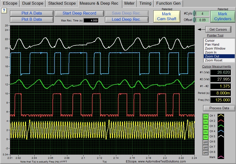
Here is another capture of a CKP on the same engine. Not as helpful, perhaps, as the bias voltage is not apparent--maybe he positive scope lead on CKP+, negative scope lead on CKP-. But maybe it will be useful for you. Crank index has a rising edge in the video. I am not sure how to access the Pico waveform library but Eric O. says he uploaded the waveform--you may be able to find it there if you have access.
It's actually possible that I may have swapped the CKP wires around. In my first removal attempt of the sensor I damaged the connector housing such that it was easier to just run jumper leads between the sensor and the harness. So the rising/falling edge issue may be corrected as soon as I hook everything up right. I have, however, tried cranking with the leads connected both ways with no change.
I think it's time to proceed with sensor replacement.
Please Log in or Create an account to join the conversation.
- ferris48
-
- Offline
- Premium Member
-
- Posts: 129
- Thank you received: 47
")
Please Log in or Create an account to join the conversation.
- lmg866
-
Topic Author
- Offline
- Junior Member
-
- Posts: 35
- Thank you received: 1
Please Log in or Create an account to join the conversation.
- lmg866
-
Topic Author
- Offline
- Junior Member
-
- Posts: 35
- Thank you received: 1
I can now definitively report that the "ENG_IMB_STAT: Locked" PID available in both ForScan and my generic scan tool is a red herring! Seeing Locked status there does not mean the engine will not start. Same for the "ENG_STRT_DIS: Yes" and "ENG_STRT_NRML: No" PIDS.
Upon removing the transmission, I found that the brass sleeve at the end of the Motorcraft sensor was hopelessly corroded inside the aluminum bore of the rear main seal retainer plate. Seeing how stuck it was, I realized that all the hours I spent trying to remove the sensor without removing the transmission were futile from the start. Removing the rear main seal retainer plate is the only way to do it. After breaking off the plastic section of the sensor, I had to drill the sleeve out of the aluminum bore, then clean the bore with an appropriately-sized wire brush in a drill to get the new sensor to slide in. The area of the new sensor that would contact the bore was coated in dielectric grease before installation.
I also noticed in the course of all this that there was a bunch of crap collected in the valley of the engine block under the intake--leaves, dirt, mouse junk. At the rear of the valley is a hole that drains this area down the back of the engine block--right onto the brass/aluminum junction of the sensor! How could this part not corrode in any kind of salted/moisture-heavy environment? My hunch is that the expansion of material caused by corrosion crushed the sensor, puncturing the insulation between the brass sleeve and the copper wire inside the sensor, and creating the short to ground that we saw.
Funny that at the end of the day, my initial hunch on day 1 with the truck--throw a crank position sensor in it--turned out to be right.
Thanks very much for the assistance on this forum! Hopefully this solved issue helps someone in the future.
Please Log in or Create an account to join the conversation.
- lmg866
-
Topic Author
- Offline
- Junior Member
-
- Posts: 35
- Thank you received: 1
Please Log in or Create an account to join the conversation.
- bills4065
-
- Offline
- Premium Member
-
- Posts: 136
- Thank you received: 16
Please Log in or Create an account to join the conversation.
- lmg866
-
Topic Author
- Offline
- Junior Member
-
- Posts: 35
- Thank you received: 1
And of course, with sensor replacement requiring transmission removal I wanted to be absolutely sure a bad sensor was the cause. Tricky situation.
The way the design is, I think others with the same F-150 platform will having the same issue. Corrosion at that location seems just about impossible to avoid, and it seems logical that the corrosion would crush the sensor and create a short to ground. I’d recommend that anyone with this platform remove their CKP sensor and grease it if it’s still easily removable!
Thanks for following along and for your thoughts along the way, bills4065!
Please Log in or Create an account to join the conversation.
- ferris48
-
- Offline
- Premium Member
-
- Posts: 129
- Thank you received: 47
Absolutely no needBy the way, ferris48, you have been a most helpful guide and have obviously spent a lot of time on this topic. If there’s a way I can PM you I’d like to arrange some token of gratitude sent your way! I’m not seeing a PM function on this forum, though.
I'm ecstatic your truck is finally running I never worked on a vehicle before and reading the immobilizer service info in identifix was pretty straight forward. Watching a couple youtube videos also helped too.Yeah me too then I read he had his scope hooked up wrongI am not above admitting I would have made a bad call, but I would have swore when you were hooked up to the positive and negative terminals with your scope on a vrs sensor and saw 1 volt -the sensor is good
In hindsight this whole thing could have been diagnosed without a scope. Key On, Engine Off, check CKP+ and CKP- wires for 2.5 volts. Both of those wire should have 2.5V or close to it. If this voltage is not there, and it returns when you unplug the sensor, then the sensor is bad. If it still won't start, try swapping the polarity. If that doesn't work, then pull out the scope for in depth analysis.
Please Log in or Create an account to join the conversation.
- lmg866
-
Topic Author
- Offline
- Junior Member
-
- Posts: 35
- Thank you received: 1
Please Log in or Create an account to join the conversation.