1996 Toyota 4runner and the Ever Popular P1300 CEL
- ZionXIX
-
 Topic Author
- Offline
- New Member
-

- Posts: 19
- Thank you received: 1
This will be my first post here. I hope to provide an interesting problem that has kept me running in circles for weeks. Any suggestions or assistance is welcome. Up to this point I have been getting most of my help from the good folks over at Toyota-4runner.org but I think they are stumped by my problem as well. So Ive decided to do a little forum jumping and heard about scanner danner in those awesome ETCG videos and decided to give it a try.
Vehicle Background:
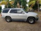
I currently drive (when she operational) a 1996 Toyota 4runner SR5 2WD with Automatic Transmission. She sports a 3.4L V6 Engine model 5VZ-FE with about 155,000 miles. This engine uses a waste spark ignition system with 3 ignition coil packs on the passenger cylinders and the waste sparks on the driver side cylinders. These 3 coil packs are wired into an Igniter module that communicates with the Engine Computer (ECU) and reports the all important Ignition confirmation signal (IGF). This information will become relevant shortly.
Environment:
She and I are attending Graduate school on an Island in the Eastern Caribbean. The island is not fully developed and thus has a less than desirable road infrastructure. We drive on a lot of dirt/gravel roads, endure harsh hurricane force storms, and enjoy lovely Maximum UV index with salty sea air. This vehicle has been student owned and pass down every couple of years. In my opinion, some of those student chose to show a little less care than others
 .
.Observations:
This all started with a symptom that I describe as "Dying at idle". One day I was idling in a parking lot checking my transmission fluid level when the engine suddenly stopped. No sputtering, no rough idle, she simply stopped. She cranked and started just fine but with a CEL illuminated on the dash board. I did not have an OBDII reader at the time so I ordered one on Amazon and kept driving in the mean time. I noticed the "Dying at idle" was happening intermittently at stops or while waiting in line at the gas station. It got to the point where I couldn't even back out of the driveway without her dying. So I parked her and waited for the scanner to come in.
Once the scanner arrived I wasted no time pulling the codes. I was greeted with a simple but unknown code to me, the P1300. My research indicated that this particular code in the regards to Toyota vehicles of this year refers to a "Igniter Malfunction Bank #1". I was not receiving any misfires, no rough idle (at least no rougher than normal), and no codes indicating spark problems. At first I was a bit confused by the "Bank #1" portion and thought it was referring to ignition coil #1 which controls spark for Cylinders 1 and 4. The obvious portion of this CEL points to the igniter module as the culprit. Turns out that part is like $400 new. I decided to wait and do some more investigating before committing to that budget breaker. I eventually found a list of possible components that can trip this code:
Igniter Module
Ignition Coils
Crankshaft position sensor
ECU (engine computer)
Spark Plugs Misfiring
Shorts in the wiring harness
Tests Performed so far:
I found a copy of the Factory service manual for this vehicle. I followed most of the troubleshooting steps that it asks for. I borrowed a multimeter and checked the following parts:
Camshaft position sensor --> within normal spec
3 ignition coils
Primary resistance --> normal
Secondary resistance --> normal
Checked continuity of wiring harness between Igniter and ECU, also between igniter and coil packs
I have verified proper voltage at the igniter
I have verified proper voltage at the IGF pin on the ECU
Parts that have been repaired or replaced:
I had ordered some parts prior to this problem occurring and went ahead and installed them in an attempt to correct the problem.
6 new OEM spark plugs
A set of new NGK low resistance ignition wires
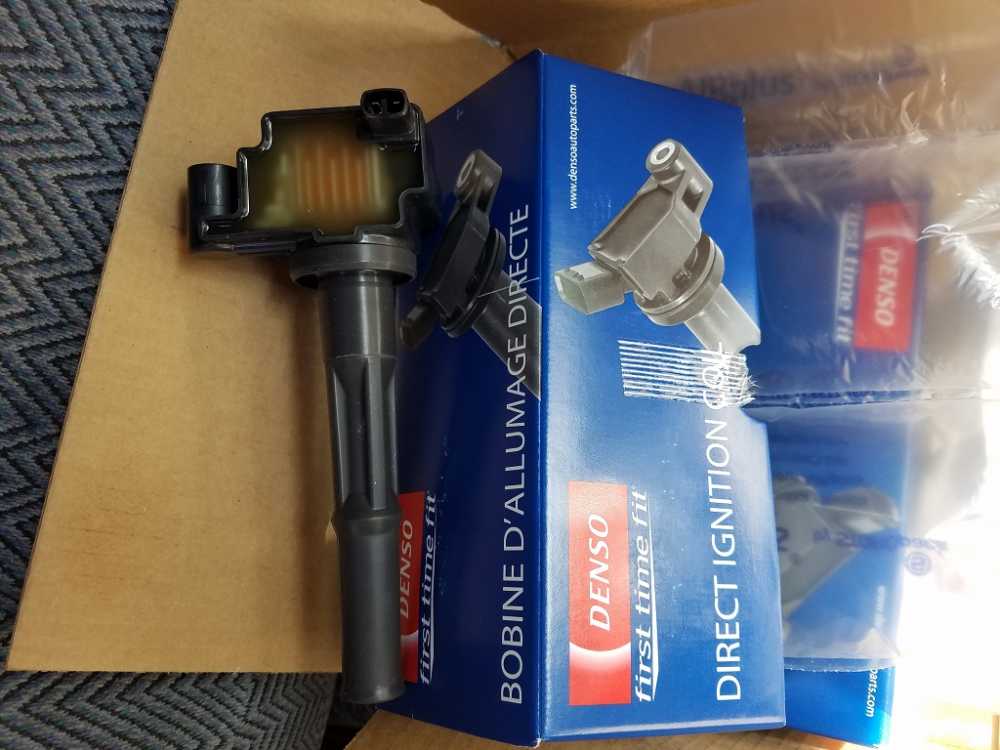
At one point it was suggested to me to replace the ignition coils even though they were within factory spec ohms. I bought 3 new Denso ignition coil for a pretty penny and installed them. This engine purrs really smoothly when its running.
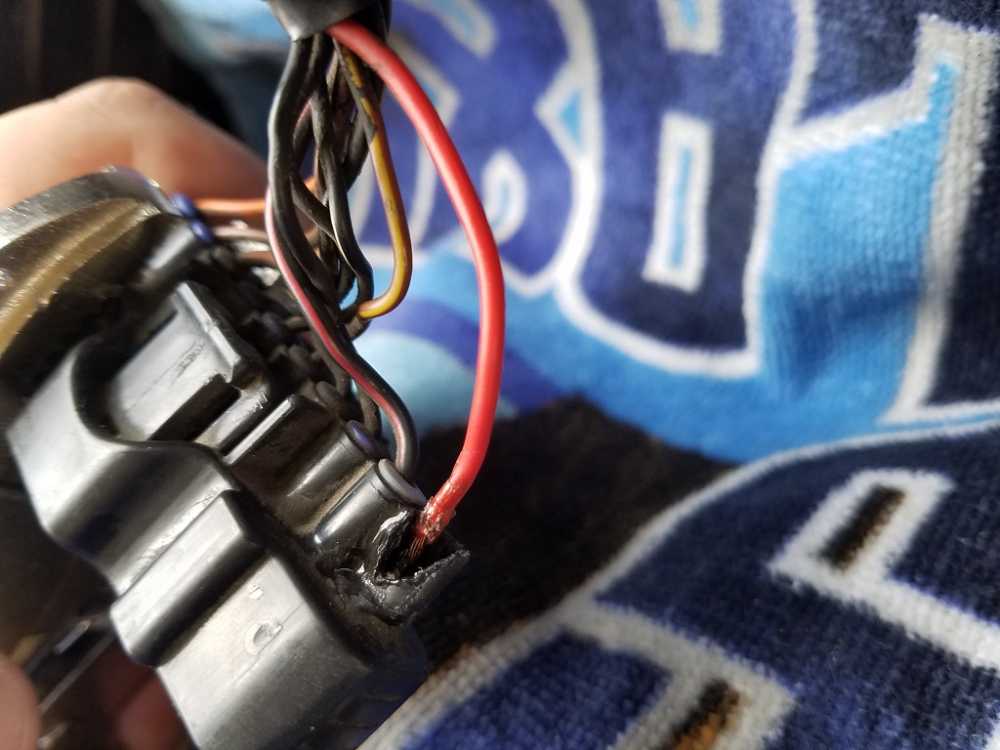
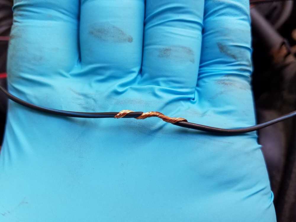
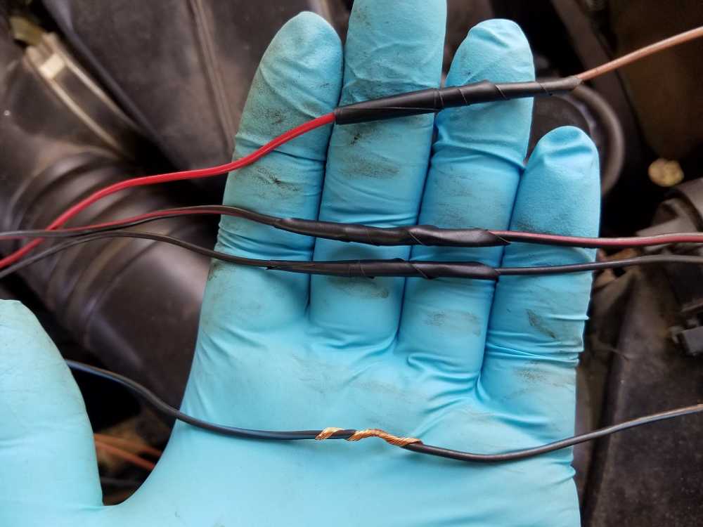
I found one of the wires on the igniter looked different and was a little loose. I pulled this wire out and opened the wiring harness to inspect and found a splice point. I soldered the wire directly to the igniter connector and soldered the splice wires and verified low resistance.
I eventually found a cheap used igniter module on ebay and swapped out my old one.

It made no difference. She starts great, runs great for about 10 to 15 seconds sometimes a whole 30 seconds and then just dies and throws that P1300 code no matter how many times I clear it.. Upon researching in the Factory service manual, the P1300 is tripped when the ECU does not receive and ignition confirmation signal after a preset number of cycles. without this signal the fuel supply is simply cut by the computer. The FSM wants me to check the IGT signal coming from the ECU while the engine is cranking. I have not performed this test yet due to lack of a 2nd person to help. I did finally get my own multimeter so I dont have to borrow anymore.
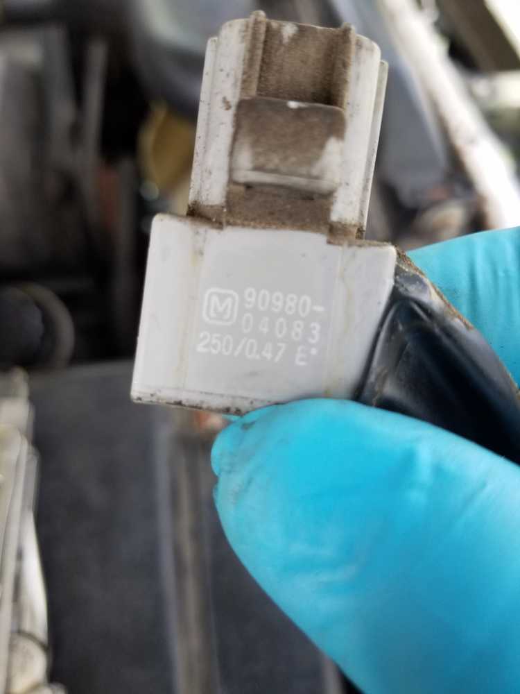
Most recently I found a part I ahve never seen before that was taped to the air intake tube out of the way. Toyota calls it a condensor, it is some sort of capacitor and apparently serves as a noise filter of some kind. I dont know if its related to the problem at hand but I put the meter on it and got infinite resistance so I think its dead and its actually fairly cheap so Ive got one coming in the mail.
I welcome any suggestions.
Thanks, -Z
Please Log in or Create an account to join the conversation.
- Tyler
-
- Offline
- Moderator
-

- Full time HACK since 2012
- Posts: 6115
- Thank you received: 1539
")
Thanks a ton for providing all the info and pictures, helps us so much when trying to point you in the right direction. These early Toyota IGF circuits were not fantastic to work on, FYI. Lots of pros have ended up pulling their hair out over stuff like this.
Unfortunately, I'm not sure how much mileage we'll get out of the multimeter in this case. A lab scope is really required to get real idea of what's going on in these IGF and IGT signals, the multimeter just isn't fast enough. Not saying we're out of luck, or to go buy one right away, just noting the limitations.
First thing that jumps out at me is the picture of the igniter connector. It looks like the pin on the end got burned. I see that you did some wiring repairs, but I'm wondering what happened to the female pin in the connector itself?
Grabbed a wiring diagram for reference, and it looks like that pin is #10, which is the #1 coil control wire. That would happen to correspond with your code description.

No offense meant here, but are you sure this red wire went back to a splice? I could have the wrong diagram, too.
My concern is that there's a voltage drop or loose pin fit at the burned female #10 pin, causing the coil control signal to drop out, creating a gap in the IGF signal, and causing the ECM to kill the fuel. Make sense?
Before going too in-depth with electrical testing, I'm wondering what that pin #10 looks like when looking into the connector itself? If you see a spread pin, or that the female pin itself has been overheated, then we may be on the right track.
Please Log in or Create an account to join the conversation.
- ZionXIX
-
Topic Author
- Offline
- New Member
-
- Posts: 19
- Thank you received: 1
Tyler wrote:
No offense meant here, but are you sure this red wire went back to a splice? I could have the wrong diagram, too.
My concern is that there's a voltage drop or loose pin fit at the burned female #10 pin, causing the coil control signal to drop out, creating a gap in the IGF signal, and causing the ECM to kill the fuel. Make sense?
Before going too in-depth with electrical testing, I'm wondering what that pin #10 looks like when looking into the connector itself? If you see a spread pin, or that the female pin itself has been overheated, then we may be on the right track.
Yes, #10 does go to coil #1. I've almost memorized that diagram. That connector didn't always look like that before. My subpar soldering skills are to blame for that one. I found a non factory splice about 3 inches into the harness most likely from a repair pin. The rubber sheath around that pin was a different color than the rest. During my early testing I wiggled that wire while the engine was running and it died when pulled a certain way. I pulled it out quite easily and tried to solder it in place with a quick and dirty solder. I've already ordered a replacement connector with a few inches of wire. I just can't imagine that the IGF signal tolerance would be so narrow that an extra ohm of resistance would throw it off. Anyway, I will be soldering all 10 wires when the connector comes in. How will that affect everything?
Thanks, -Z
Please Log in or Create an account to join the conversation.
- Andy.MacFadyen
-

- Offline
- Moderator
-
- Posts: 3357
- Thank you received: 1037
" We're trying to plug a hole in the universe, what are you doing ?. "
(Walter Bishop Fringe TV show)
Please Log in or Create an account to join the conversation.
- ZionXIX
-
Topic Author
- Offline
- New Member
-
- Posts: 19
- Thank you received: 1
Andy.MacFadyen wrote: One thing I would check is if you still have a control signal at the injectors when the engine stalls, if injector signal disapears at the same time as the engine cuts then I would look toward the crank sensor and its wiring.
I will admit I have no idea how to check the control signal at the injectors. The fuel is intentionally cut to stop the engine due to the P1300 conditions. The crankshaft sensor is showing factory spec for resistance so it should be working normally. I guess I'm just not convinced of any problems with the crank sensor. If you can elaborate on how to test those components, I'm willing to try it.
Please Log in or Create an account to join the conversation.
- ZionXIX
-
Topic Author
- Offline
- New Member
-
- Posts: 19
- Thank you received: 1
ZionXIX wrote:
Tyler wrote:
No offense meant here, but are you sure this red wire went back to a splice? I could have the wrong diagram, too.
My concern is that there's a voltage drop or loose pin fit at the burned female #10 pin, causing the coil control signal to drop out, creating a gap in the IGF signal, and causing the ECM to kill the fuel. Make sense?
Before going too in-depth with electrical testing, I'm wondering what that pin #10 looks like when looking into the connector itself? If you see a spread pin, or that the female pin itself has been overheated, then we may be on the right track.
Yes, #10 does go to coil #1. I've almost memorized that diagram. That connector didn't always look like that before. My subpar soldering skills are to blame for that one. I found a non factory splice about 3 inches into the harness most likely from a repair pin. The rubber sheath around that pin was a different color than the rest. During my early testing I wiggled that wire while the engine was running and it died when pulled a certain way. I pulled it out quite easily and tried to solder it in place with a quick and dirty solder. I've already ordered a replacement connector with a few inches of wire. I just can't imagine that the IGF signal tolerance would be so narrow that an extra ohm of resistance would throw it off. Anyway, I will be soldering all 10 wires when the connector comes in. How will that affect everything?
Thanks, -Z
I need to make a correction and add a little more inormation here:
I have tested the resistance of the IGC wires from the igniter to the coils. Coil #1 showed 0.5 ohms, Coil #2 --> 0.3 ohms, and Coil #3 --> 0.3 ohms. Could a difference of 0.2 ohms really cause a huge drop in IGF signal?
Please Log in or Create an account to join the conversation.
- ZionXIX
-
Topic Author
- Offline
- New Member
-
- Posts: 19
- Thank you received: 1
My new igniter connector arrived in the mail finally :woohoo: . I ordered it 3 weeks ago :S . Anyway, I was really excited to install it and see if it fixed my problem. Due to time constraints I did not have time to solder the wires. I chose instead to simple twist and tape. I tried to make them as strong as possible. Unfortunately this did not fix my problem. P1300 still pops up. I even swapped out the igniter for my old one and still has the same issue. I checked the new wires for continuity. The ignition coil wires all stayed between 0.4 and 0.5 ohms. Im sure the unspliced harness would have a similar value. So chime in if you have any ideas.
Thanks, -Z


Please Log in or Create an account to join the conversation.
- ZionXIX
-
Topic Author
- Offline
- New Member
-
- Posts: 19
- Thank you received: 1
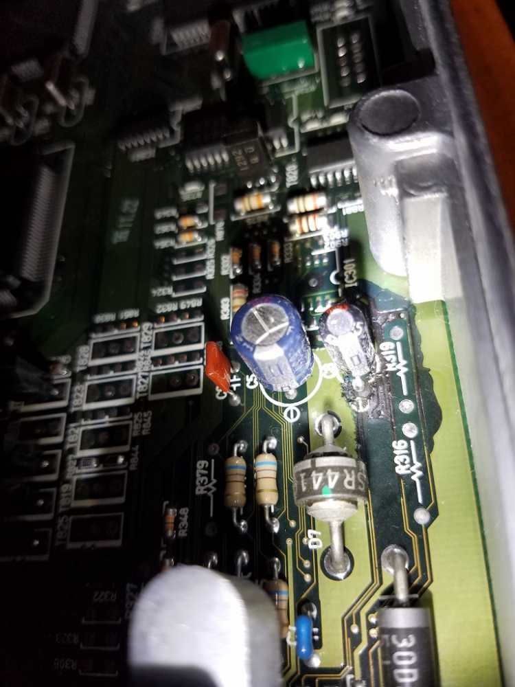
The guys over at T4R suggested that I remove the ECM and do a visual inspection since I do not have an oscilloscope. I snapped a couple of photos of the PCB board and I think 1 or more of the capacitors has spewed its entrails onto the PCB. Let me know what you guys think.
Here are some links to my dropbox photos so you can get a nice large picture to zoom in on.
Back
www.dropbox.com/s/msbhon7qceu71l3/20160907_192612.jpg?dl=0
www.dropbox.com/s/47ydujyxuzaui7b/20160907_192714.jpg?dl=0
Front
www.dropbox.com/s/lq0w4jwezovt2so/20160907_192803.jpg?dl=0
www.dropbox.com/s/a3bxkeyudtpdeuc/20160907_192807.jpg?dl=0
Suspect area on front side
www.dropbox.com/s/bgmzih896nbkm0u/20160907_192912.jpg?dl=0
www.dropbox.com/s/9vodd8mnyyh611h/20160907_192937.jpg?dl=0
Thanks, -Z
Please Log in or Create an account to join the conversation.
- Caritech
-

- Offline
- Premium Member
-

- Posts: 115
- Thank you received: 10
Please Log in or Create an account to join the conversation.
- ZionXIX
-
Topic Author
- Offline
- New Member
-
- Posts: 19
- Thank you received: 1
Caritech wrote: Keep this low tech. Can you switch the coils around? I had a Corolla come to the shop that would stall @ operating temp. I had no scope at the time so I had to rely on scan tool data, which was the p1300 code for 1, 3 and 4. I cleared them, ran the car till it died and got only for 3, cleared again and the code returned for the same cylinder. I switched coils 3 and 4 and code moved to 4 when car died. Got a coil pit of scrap yard and owner messaged me 1 week later to report issue was gone.
All coils, plugs, and wires are brand new.
Please Log in or Create an account to join the conversation.
- ZionXIX
-
Topic Author
- Offline
- New Member
-
- Posts: 19
- Thank you received: 1
The T4R guys have asked me to take a little closer look at the MAF. I have paid any attention to the MAF other than cleaning it. It hasnt given me any codes so I have just been ignoring it. This particular MAF is an older style "windtunnel" design that can be found on older tacomas, avalons, and camrys to my surprise. Anyway there are 5 pins. I dont know which pins do what since I have an FSM for a 2002 which uses a newer updated MAF with a different pin order. Pin #1 in my mind is next to the airbox towards the front of the vehicle. Pin #5 is on the air tube side towards the back of the vehicle.
Pins 3 and 4 give me 1,996 ohms --> despite the FSM saying nothing about checking those pins for resistence
Checked voltage on pins 2 and 4 with ignition on. Got a steady 11.27volts that would occasionaly changed to 11.26. Blowing into the MAF made absolutely no difference. So is the MAF dead? or do I need the ECM connected to induce a voltage change?

Please Log in or Create an account to join the conversation.
- ZionXIX
-
Topic Author
- Offline
- New Member
-
- Posts: 19
- Thank you received: 1
No need for pics here, just more of the same. So I reconnected the ECM and got very different voltage readings. When I cover the hole I get 0.585ish volts that hold steady. When directly blowing into the hole the voltage spikes as high as 3.1 volts. As long as its within normal range, I would say i have fully functioning MAF. Which is just one more thing I can cross off the check list. So you definitely need the ECM connected to observe the voltage changes.
Please Log in or Create an account to join the conversation.
- ZionXIX
-
Topic Author
- Offline
- New Member
-
- Posts: 19
- Thank you received: 1
I am really tempted to try and replace those capacitors and buy extras for the remaining. I have been researching this. The capacitors are extremely cheap, even for the high quality 5000hr ones. That link I posted about replacing capacitors on a Lexus ECU is extremely detailed on what kind of caps and where to get them. I already have an iron, solder, and Flux. I would like to get a solder pump and some Flux wire. I found a kit on amazon for less than $10. If it doesn't work, I am about ready to replace the ECU anyway.
Please Log in or Create an account to join the conversation.
- Tyler
-
- Offline
- Moderator
-
- Full time HACK since 2012
- Posts: 6115
- Thank you received: 1539

It's a '98, in for a water pump. I'm hoping I'll have some time after I get the repairs done to do some scope tests on the IGT/IGF signals. I didn't get too much time to play with it, since it was dumping coolant out faster than I could put it in, lol.
I see what you mean about the failed capacitors on the ECM board
 I was honestly still suspicious of an intermittent connection issue, but now I kinda do suspect an internal problem. My only concern with replacing the capacitors themselves is if the board has been damaged already. But, if you're ready to do the ECM anyway, then I say go for it!
The MAF could totally account for the stall, but not for the P1300, IMO. I've disconnected those sensors while the engine is running, and never generated anything but MAF codes, so I think you're good there.
Please Log in or Create an account to join the conversation.
- ZionXIX
-
Topic Author
- Offline
- New Member
-
- Posts: 19
- Thank you received: 1
Tyler wrote: Sorry for not getting back to you sooner, crazy week. In other news, look what just showed up in my bay!
It's a '98, in for a water pump. I'm hoping I'll have some time after I get the repairs done to do some scope tests on the IGT/IGF signals. I didn't get too much time to play with it, since it was dumping coolant out faster than I could put it in, lol.
I see what you mean about the failed capacitors on the ECM board
The MAF could totally account for the stall, but not for the P1300, IMO. I've disconnected those sensors while the engine is running, and never generated anything but MAF codes, so I think you're good there.
Nice! I can't wait to read about your findings if you have any.
The capacitors are so cheap I may buy several of type. I only count 4 on this board. Gotta love the simplicity. I'm also considering buying a used ecu that has no damage and replacing the capacitors as preventative maintenance. I'd like to think of it as the poor man's rebuild.
Happy Saturday
Please Log in or Create an account to join the conversation.
- Tyler
-
- Offline
- Moderator
-
- Full time HACK since 2012
- Posts: 6115
- Thank you received: 1539
Please Log in or Create an account to join the conversation.
- ZionXIX
-
Topic Author
- Offline
- New Member
-
- Posts: 19
- Thank you received: 1
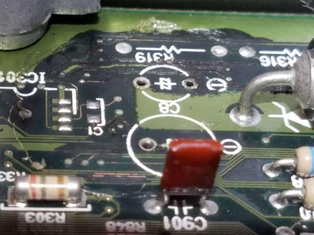
Hey guys, it's been a while since I've posted. I finally received all necessary parts and I'm beginning to make progress. I'm trying to take my time since this is a sensitive repair job. Up until this post I have removed the 2 suspect capacitors. 1 capacitor was blown, the other appeared intact. I wasnt sure until I removed them. I have a couple of progress pictures and some questions.
It was suggested to me that I use alcohol and cotton swabs or a tooth brush to clean off the electrolytic fluid. This stuff is dry, crusty and extremely stuck on. I'm scrubbing really hard without much removal. Lastly I tried using a small jewelers flat head screw driver to scrape the material away using as little pressure as possible. Just the weight of tool. Is this a bad idea? What happens if I leave some fluid behind?
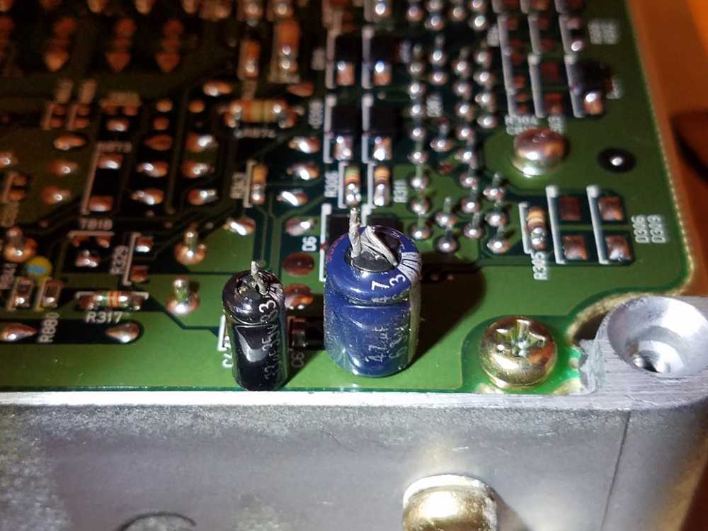
Before cleaning
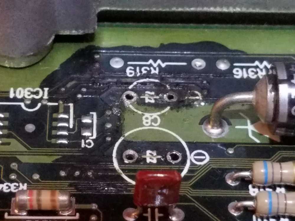
During Cleaning
Please Log in or Create an account to join the conversation.
- ZionXIX
-
Topic Author
- Offline
- New Member
-
- Posts: 19
- Thank you received: 1
I wanted to update this thread. I ordered a used ECU to replace mine and that fixed my P1300 issue. I tried to repair the board with the help of the community but was unsuccessful. I know this site is all about testing before replacing but i simply did not have access to the tools I needed for proper diagnosis of the problem. I did waster a lot of time and money replacing other parts that did not need replacing. If anyone else is having this problem on this same vehicle, I would just follow the instruction in the Factory service manual. Im glad to have the 4runner back on the road and I do appreciate the help you guys provided me. If anyone is interested in reading more, I have an extensive thread on the T4R.org site. I also updated the thread title to reflect the "solved" status.
www.toyota-4runner.org/3rd-gen-t4rs/2224...pular-p1300-cel.html
Thanks, -Z
Please Log in or Create an account to join the conversation.
- Noah
-
- Offline
- Moderator
-
- Give code definitions with numbers!
- Posts: 5008
- Thank you received: 1116
Glad you got it figured out!
"Ground cannot be checked with a 10mm socket"
Please Log in or Create an account to join the conversation.