Help us help you. By posting the year, make, model and engine near the beginning of your help request, followed by the symptoms (no start, high idle, misfire etc.) Along with any prevalent Diagnostic Trouble Codes, aka DTCs, other forum members will be able to help you get to a solution more quickly and easily!
Took car for test drive. Ran good for about two blocks then lost gas pedal function. Coasted back home and attached Solus pro and retrieved 3 codes. P2127, P0606 & P2138. Talked to car owner and he explained that his uncle had bought car from him and he had someone else work on it. They replaced the accelerator pedal position sensor (looks used), ECM and other parts but didn't know what parts. I did a visual inspection and found that the wires at the TPS were all attached with connectors so I can only assume that they also replaced the TPS. I cleared the codes then turned on the car, check engine light came back on after pressing gas pedal a few times. checked codes and only P2138 came on. I turned car off and checked wire harness connection at pedal and TPS (wiggle test) and cleared the codes again. I turned on the vehicle and engine light came back on. Checked codes and now P2127 is on. I am attempting to follow the Mitchell check table for code P2127 but at step 2 it asks to observe the APP sensor 2 voltage with scan tool and if it's less than .26 V. The Volts on scan tool are 0. would you interpret 0 Volts as yes it is less than .26 V or no there is no reading and something is wrong?
Pretty sure there is a service bulletin for throttle bodies on these, at least for the CTS. I have done several. Throttle body & new wiring harness end. Parts are cheap, from the Rock.
Give us the model & engine & I will see if I can find the bulletin.
Last edit: 8 years 9 months ago by arbez. Reason: Cant spell
Like arbez said, we can offer a lot more model specific info if you let us know the make and model you're working with.
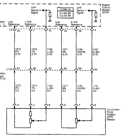
With the codes coming back immediately, I'd probably go direct to the APP itself for some pinpoint tests. I grabbed a CTS with a 3.2L engine for an example:
With the key on and the APP plugged in, measure voltage at the APP2 pins. One should be 5V, one should be zero, and one should be something other than zero. The Snappy Troubleshooter says APP should range from .49 - 2.08V (for a CTS 3.2L). Let us know what you find.
I don't remember which was which but I think it was app1 should read close to 4.5v at 0% throttle and app2 should read close to .5v at close throttle as throttle pedal is pressed the 4.5v will go down and the .5v sensor will go up. The total of app1 and app2 should equal 5v at all times if you have 0v on either than check your 5v reference
Thanks for replying. I found the service bulletin and this CTS Caddie already has the upgrade. It has the new throttle body acceleration wire harness. I checked for voltage drop before and after each of the 6 wire connectors and they are all fine.
RickD. wrote: Thanks for replying. I found the service bulletin and this CTS Caddie already has the upgrade. It has the new throttle body acceleration wire harness. I checked for voltage drop before and after each of the 6 wire connectors and they are all fine.
There was a batch of the early replacement TB's that were defective. After a few months they had issues again. Just because it has been replaced doesn't mean that it is good. Check, just to be sure.
RickD. wrote: Thanks for replying. I found the service bulletin and this CTS Caddie already has the upgrade. It has the new throttle body acceleration wire harness. I checked for voltage drop before and after each of the 6 wire connectors and they are all fine.
Do you recall what the APP readings were? 'Cause it sure sounds like a faulty APP, or the wiring to it.
I disconnected the APP wire harness per Mitchell Diagnose flow chart for 3.6 engine. I checked volts for both sensor 1 and sensor 2 of the APP. Both had 1 wire with 4.99 volts , 1 wire with .7 volts and 1 wire of each had 0 volts. I checked resistance between the APP and the ECM on both wires with 0 volts and both with 5 volt and all read .8 ohms. I connected the solus pro, cleared the code and checked the APP reading on scanner and it went from 0 to 100 with ignition on engine off as I depressed the pedal. I then turned on the car and depressed the gas pedal and the APP reading would jump from 20 to 0 or from 10 to 0 readings were erratic and the check engine light turned back on. Is .8 ohms of resistance on the 4 wires between the APP and the ECM good readings? The reason why I checked resistance is because the flow chart step 9 says to test the 5 volt reference circuit of APP sensor 2 for a short to ground, high resistance or an open circuit. How would I check for a short to ground and for an open circuit?
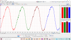
OK gentlemen, I connected (back probed) vantage pro leads to APP connector and followed the APP DC test. read 0 v on sensor 1 and .001 v on sensor 2 with key off.I turned ignition on engine off and got .01 v on sensor 1 and .46 v on sensor 2. depressed gas pedal and volts increased on both sensors. The graph wave looked smooth going up and down with pedal movement. Turned engine on and depressed pedal and now the graph wave had lines dropping from the wave tops but not on all of them. I turned the key off and removed it and noticed that the same volts were reading as when I had the ignition on engine off. Stayed this way for a few minutes. Is it normal for the APP to keep reading volts after key is removed? Are the drops in the wave form while engine is running indicating that the APP is bad or should I go with the wave form of key on engine off? I really appreciate your support. Thanks - Rick D.

 Topic Author