[FIXED] Explorer no spark - confirm my diagnosis
- Exranger06
-
 Topic Author
- Offline
- Junior Member
-

- Posts: 22
- Thank you received: 2
The engine cranks over fine; it just doesn't start. It's not a fuel issue because I can hear the pump turn on when I turn the ignition on, and I hooked up my fuel pressure tester and I get 65 psi at the fuel rail. Also not a PATS issue as the theft light does not blink rapidly when cranking and there are no codes for PATS.
I hooked up a spark tester to one of the plug wires and there's no spark. Plugs and wires are new. I tested the coil pack by checking the resistance on the primary and secondary sides and it's within spec. I even threw another coil on just to be sure and still no spark.
Then I checked the connector that plugs into the coil. One of the pins has +12V like it should. I used an LED test light to see if the computer grounds out the other pins while cranking the engine. No flashing light, no signal from the computer.
The computer tells the coil to fire when it senses the engine is cranking. It knows when the engine is cranking when the crankshaft position sensor sees the crank rotating. So, the crank sensor was my next suspect. It's worth noting that the tach doesn't move at all while cranking, and the live data on my scanner shows 0 rpm while cranking. I know the computer is turning on because the check engine light turns on, the fuel pump turns on, and my scanner communicates with it when the ignition is on.
So at this point I have the problem narrowed down to either a bad crank sensor, a bad computer, or a problem with the wiring between the crank sensor and computer. (Unless I'm missing something?)
Then, I replaced the crank sensor and still no spark. I even replaced it again (with a Motorcraft part), thinking maybe I got a defective new one. Still no start. I think i can cross bad crank sensor off the list.
I found a pinout of the ECM online, found which wires at the ECM connector go to the crank sensor, and checked for continuity at either end of the wires. I have good continuity. Cross wiring problem off the list.
The only thing left is a bad ECM. Does everyone agree with my diagnosis? Anything else it could be?
Please Log in or Create an account to join the conversation.
- Caritech
-
- Offline
- Premium Member
-

- Posts: 115
- Thank you received: 10
How the ECM knows to keep the pump going? It needs the CKP for that. Correct? This would prove good rpm signal to ECM.
Please Log in or Create an account to join the conversation.
- Exranger06
-
Topic Author
- Offline
- Junior Member
-
- Posts: 22
- Thank you received: 2
The crank sensor is a 2 wire.
I also agree the coil is good. The fact that I'm not getting any pulsing ground at the coil connector tells me that the real problem is the computer is not telling the coil to fire, not a bad coil.
Yes, the ECM needs a crank signal to keep the fuel pump going. I'm not sure if that's happening because I can't hear the fuel pump over the sound of the engine cranking. But I already know the ECM isn't getting a crank signal because I'm not seeing any RPM on the tach or the scanner, and it's not telling the coil to fire.
Please Log in or Create an account to join the conversation.
- Tyler
-
- Offline
- Moderator
-

- Full time HACK since 2012
- Posts: 6115
- Thank you received: 1539
LOVE the testing you've done so far, makes it way easier for us to help. Not sure if you've checked for this yet, but you can use the check engine light as a guide on Fords of this generation. Skip to about 4:50 to see what I'm referring to. I know, this video revolves around no fuel pressure (and you have it), just using it as an example for demonstration purposes.
Seeing the light work as designed would give you even more confidence in the crank sensor circuit, and the PCM. If the light doesn't go out, then we can go further into the crank sensor. No light at all would be a strike against the PCM. FYI, I usually find that Fords don't update the RPM PID during cranking.
Like Caritech suggested, checking the 5V reference circuit would be another good test for PCM health. I think the DPFE sensor is out in the open on this engine? Beneath the IAC motor? Turn the key on, disconnect the sensor, and use a multimeter to check for voltage. At least one of the three wires should have 5V on it.
Let us know what you find with the CEL and 5V tests, and we'll come up with further testing!
Please Log in or Create an account to join the conversation.
- Caritech
-
- Offline
- Premium Member
-
- Posts: 115
- Thank you received: 10
Please Log in or Create an account to join the conversation.
- Noah
-

- Offline
- Moderator
-
- Give code definitions with numbers!
- Posts: 5006
- Thank you received: 1116
Nice work so far.
"Ground cannot be checked with a 10mm socket"
Please Log in or Create an account to join the conversation.
- Exranger06
-
Topic Author
- Offline
- Junior Member
-
- Posts: 22
- Thank you received: 2
Please Log in or Create an account to join the conversation.
- Tyler
-
- Offline
- Moderator
-
- Full time HACK since 2012
- Posts: 6115
- Thank you received: 1539
Exranger06 wrote: Ok, so the check engine light stays on while cranking. The DPFE sensor connector has 5V on two of the three pins.
OK, nice! The PCM still isn't seeing an RPM signal. Seeing two 5V pins at the DPFE is what I hoped for, as it uses a bias line on the signal wire. Totally normal.
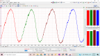
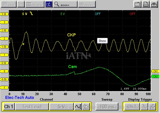
Pretty sure this engine will run without the camshaft position sensor, so I'm not too worried about that. I think the next step is some CKP voltage measurements at the PCM during cranking. I know you installed a new OE sensor, AND tested the wires, but there's still something wrong here.
For reference, I grabbed a known good cranking CKP waveform from iATN:
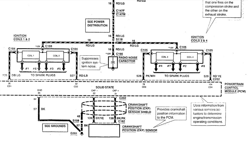
I know that Exranger06 knows which pins to test at the PCM, but here's a circuit diagram for anyone else following along:
If you haven't seen it already, this ScannerDanner video demonstrates what we're looking for perfectly. Different engine, but the design of the sensor is identical.
Not sure if you have a scope available. If not, not a problem, your DVOM will work just fine. Connect your test leads across both backprobes and switch the DVOM to AC voltage. Crank the engine and look for a reading. How much voltage you'll see will depend on cranking speed, but I'd *guess* you're looking for around 500mV. Obviously, 0V would represent a problem.
The design of this sensor circuit is somewhat unique (read: weird), so please don't hesitate to ask questions about doing this test!
Please Log in or Create an account to join the conversation.
- cheryl hartkorn
-
- Offline
- Platinum Member
-

- Posts: 694
- Thank you received: 130
Please Log in or Create an account to join the conversation.
- Tyler
-
- Offline
- Moderator
-
- Full time HACK since 2012
- Posts: 6115
- Thank you received: 1539
cheryl hartkorn wrote: maybe remove the crank sensor use a piece of metal and wave the crank sensor over it back and forth while checking for spark while doing that.
Ooooh yeah, I like your thinking here! I remember an article in Motor Age a few years ago about a failed harmonic balancer on a similar Explorer, resulting in the CKP tone wheel (on the balancer) shifting out of line from the CKP sensor. That'd definitely account for no crank signal...
depending on equipment you have id be tempted to unhook both end of the crank sensor circuit put power on the wires and load the circuit. to rule out the wires for sure.
Thought about suggesting this, too. Only thing I'd add is using a test light to B+ to check for a short to ground before adding power, just to play it safe.
Please Log in or Create an account to join the conversation.
- cheryl hartkorn
-
- Offline
- Platinum Member
-
- Posts: 694
- Thank you received: 130
Please Log in or Create an account to join the conversation.
- Exranger06
-
Topic Author
- Offline
- Junior Member
-
- Posts: 22
- Thank you received: 2
Please Log in or Create an account to join the conversation.
- Exranger06
-
Topic Author
- Offline
- Junior Member
-
- Posts: 22
- Thank you received: 2
I back-probed the crank sensor wires at the ECM, hooked up my multimeter (set multimeter to V AC), turned the ignition on, (don't think that makes a difference, but thought I'd mention it) and cranked the engine with the remote starter button. I'm getting 0V when not cranking, and when cranking, the voltage fluctuates between 0.5 V and 0.75 V. Looks like the signal is getting to the ECM, but the ECM isn't doing anything with it. I'm thinking my original diagnosis of a bad ECM is correct. Thoughts?
Please Log in or Create an account to join the conversation.
- ScannerDanner
-

- Offline
- Administrator
-

- Religion says do, Jesus says done!
- Posts: 975
- Thank you received: 500
Don't be a parts changer!
Please Log in or Create an account to join the conversation.
- Exranger06
-
Topic Author
- Offline
- Junior Member
-
- Posts: 22
- Thank you received: 2
Please Log in or Create an account to join the conversation.
- Tyler
-
- Offline
- Moderator
-
- Full time HACK since 2012
- Posts: 6115
- Thank you received: 1539
Exranger06 wrote: OK, I will check for injector pulse. I assume an LED test light will work for this? (Basically same procedure as checking for pulsing at the ignition coil connector, correct?) Is it necessary to check all of the injectors, or just one? If I have injector pulse, does that mean the ECM is good?
Yep, LED will work for this test. Just checking one will tell us what we want to know. For clarification, check out this video for injector pulse testing. Skip to around 2:10. It's a Honda in the video, but the steps are identical.
I'm actually very surprised to hear that you've got crank sensor voltage at the PCM! My money was on a bad connection, despite the ohm test. Thanks for doing that test, as it answers a lot of questions regarding the crank sensor.
One way I can think of to explain how the crank sensor is functional but isn't getting to the PCM would be a spread pin at the PCM connector itself. Unlikely, I know, but possible.
The easiest way to check for this would be a visual on the pins themselves, on both sides. I also know that these Ford VRS sensors use a floating ground on their sensor wires, hence we had you connect the multimeter across both sensor wires. I'd be interested to know if the floating ground voltage is present with the key on. For this, you'd connect your multimeter ground to B-, and check both crank signal wires for DC voltage. A lack of floating ground voltage would indicate a problem.
Please Log in or Create an account to join the conversation.
- Exranger06
-
Topic Author
- Offline
- Junior Member
-
- Posts: 22
- Thank you received: 2
Please Log in or Create an account to join the conversation.
- Tyler
-
- Offline
- Moderator
-
- Full time HACK since 2012
- Posts: 6115
- Thank you received: 1539
 The spread crank sensor pins are the last thing I can think of. It'd be good to check powers and grounds, but I have a hard time seeing that being the cause.
Just curious, there'd been no wiring repairs at the crank sensor connector? I've heard of these connectors getting repinned backwards, resulting in a signal polarity problem, but never seen it personally.
Please Log in or Create an account to join the conversation.
- Exranger06
-
Topic Author
- Offline
- Junior Member
-
- Posts: 22
- Thank you received: 2
I actually jumped the gun a little and already ordered a replacement ECM. Junkyard unit, ordered off eBay. Same part number and calibration code as the one I have, and (according to seller) also from a 1999 Explorer with 4.0 OHV and auto trans. Should be a perfect match. And since these rarely fail, it's most likely not defective. Only $18 with free shipping. The only real pain is going to be reprogramming the PATS. I found a locksmith shop that said they'll try to do it for $50, but I have to tow the Explorer about 17 miles to their shop. The other option is the Ford dealer 5 miles away, but I have no idea how much they'll charge. I haven't found any locksmith that can do this on site around here.
I'm going to check out the floating ground and the battery cables before towing the truck anywhere, as well as anything else you guys think I should do.
Please Log in or Create an account to join the conversation.
- Tyler
-
- Offline
- Moderator
-
- Full time HACK since 2012
- Posts: 6115
- Thank you received: 1539
If we're on the right track with a PCM, then I think you'll end up with spark but no injection pulse, due to the PATS of course. The CEL should also go out during cranking. That'll be the green flag to do the theft relearn.
Thanks for staying with us, sir! I hope we didn't make you feel like we doubted your diagnosis, just wanted to explore every possibility.
Please Log in or Create an account to join the conversation.