1997 Mitsubishi Montero Sport Rough Idle, Lack of Power, P0300
- shepherdguy
-
 Topic Author
- Offline
- New Member
-

- Posts: 18
- Thank you received: 0
To continue, I backprobed at the power transistor and have no test light pulse on the bad feed. And in case it makes any difference, I did swap the coils and the problem did not follow the coil (coils were returned back to their original location). I followed a mfg. procedure from AllData for testing continuity on the Ignition Power Transistor using a 1.5v power supply and all three drivers pass continuity. Using the test light I checked for voltage between the PCM and Power Transistor and get a good strong light from the two good feeds but a weak light from the bad feed at both the PCM and Power Transistor ends of the wire. Everything, to me, seemed to point to a driver in the PCM. I tried to get feedback from a couple of Mitsubishi-experienced mechanics on JustAnswer.com and both seemed to agree that the problem was the PCM. So I went ahead and replaced the PCM but I still have the same issue.
I just don't know if there is something on the other side of the PCM I am over looking or if I potentially popped the driver in the new PCM? Resistance on all three wires between the PCM and Power Transistor are all the same (0.4 ohms) I even tried to temporarily replace the wire between the PCM and Power Transistor and it made no change.
If I did pop the driver in the new PCM, then I need help in troubleshooting the cause. I did review a video Paul Danner posted about a vehicle that had a coil with high amps that may have fried the PCM. I'm thinking I may possibly have the same or similar issue. But again, I do not have a scope w/ amp probe and attenuator to check waveforms. Can someone please help? I cannot replace the PCM again without determining root cause or even determining for sure if it is the PCM. I know Paul is the master with this but I also know he is very busy and cannot possibly answer each person needing help. I am praying someone out there can lead me in the right direction.
By the way, I did check the resistance on both the primary and secondary sides of all three coils and all three are within mfg. specifications but I know that Paul doesn't put a lot of stock in coil resistance readings. Any thoughts or advice???
Please Log in or Create an account to join the conversation.
- Tyler
-
- Offline
- Moderator
-

- Full time HACK since 2012
- Posts: 6115
- Thank you received: 1539
For my reference (and others following), this is the ignition system wiring diagram:

I'm a bit confused about your testing, since you mention testing battery feeds at the PCM and power transistor, but neither one provides battery power on this circuit. The ignition coil primary control wires at pins 11, 12 and 13 can and should pulse a test light connected to B+, but none of the PCM control wires at pins 1, 2 and 3 will. Those are low current 0-4V square waves produced by the PCM. I'm really not trying to lecture! Just want to make sure I understand the testing you've done.
Using the test light I checked for voltage between the PCM and Power Transistor and get a good strong light from the two good feeds but a weak light from the bad feed at both the PCM and Power Transistor ends of the wire.
I think you hit the nail on the head with this test, but I just want to clarify. When you got a weak light, which pin were you touching, and what polarity was your test light connected to?
FYI, I've personally seen two different Montero's with the 3.0L have this exact same symptom, and in both cases it was due to a jumped timing belt.
") With the timing out, the cam/crank signals get out of sync, and the PCM stops sending a trigger signal for one of the coils, and you wind up with a two cylinder misfire.
With the timing out, the cam/crank signals get out of sync, and the PCM stops sending a trigger signal for one of the coils, and you wind up with a two cylinder misfire.Why doesn't it set cam/crank codes? Good question. :lol: Anyway, before you go much further, I'd suggest pulling the two upper timing belt covers and see if you can line up the timing marks. The other common issue is the crankshaft sensor reluctor slipping off the crank sprocket. The reluctor is roll pinned to the sprocket, and have a tendency to shear off. If this happens, you end up with correct timing belt marks, but an incorrect cam/crank relationship.
Please Log in or Create an account to join the conversation.
- shepherdguy
-
Topic Author
- Offline
- New Member
-
- Posts: 18
- Thank you received: 0
Another thing I had done is check powers and ground for both CKP and CMP. I then hooked a voltmeter up to the reference wire (one at a time) and with the coils all unplugged, I manually turned the crank shaft by hand bit by bit until 5V read on the meter. I used chalk to mark on the crank pulley where the 5v picked up and where it dropped. I ended with three equally sized and equally spaced chalk marks, which theoretically indicate the CKP sensor is working the way it should. I did the same with the CMP sensor but the marks don't raise or drop with one crank revolution, it would take two revolutions so I got confused with the chalk marks but it did appear to be turning voltage on and off correctly so I think the sensors are both good - it's just the timing of the two that's in question.
Please Log in or Create an account to join the conversation.
- shepherdguy
-
Topic Author
- Offline
- New Member
-
- Posts: 18
- Thank you received: 0


Please Log in or Create an account to join the conversation.
- Tyler
-
- Offline
- Moderator
-
- Full time HACK since 2012
- Posts: 6115
- Thank you received: 1539
shepherdguy wrote: Thank you for the reply and sorry for the confusion. I got pulse on the test light (Bat+) on the wires between the coils and Ignition Power Transistor for 12 & 13, but not 11. On the other side of the Power Transistor, and with Test Light still on Bat+, I get the test light to illuminate on 2 & 3, but not 1. Same results when back-probing at the PCM - test light illuminates on 10 & 23, but not 11 (these are ground-side triggered it would appear?).
Wow. :blink: :lol: Thanks for the clarification! 'Cause I'm very surprised to hear that the PCM control circuits pulsed a test light connected to B+. Every Montero I've tested used positive voltage pulses to signal the Power Transistor to fire, so I'm wondering how the test light is finding a ground... Perhaps the circuit design is different on this one? :huh:
Also, my apologies, sir. I didn't know you'd been into the timing already. :blush:
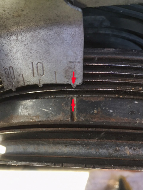
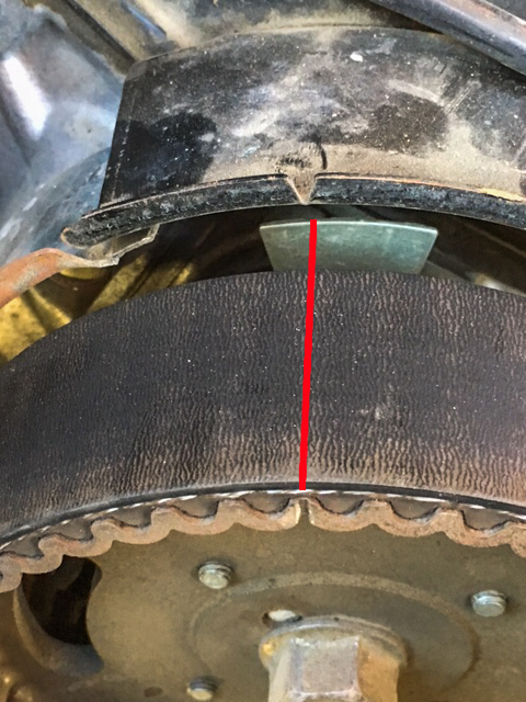
But the notch on crank reluctor wheel was off slightly. I took a picture of it to get a better look and I noticed dark markings where the crankshaft gear used to be lined up in relation to the reluctor, indicating the plate has slipped from position.
Good eye.
") Let us know what you find! If possible, you can also try using a screwdriver to turn the reluctor independent of the crank sprocket? Obviously, if you can spin it, then there's a problem.
Let us know what you find! If possible, you can also try using a screwdriver to turn the reluctor independent of the crank sprocket? Obviously, if you can spin it, then there's a problem. Please Log in or Create an account to join the conversation.
- matt.white
-
- Offline
- Elite Member
-

- Posts: 220
- Thank you received: 29
Sent from my iPhone using Tapatalk
Please Log in or Create an account to join the conversation.
- shepherdguy
-
Topic Author
- Offline
- New Member
-
- Posts: 18
- Thank you received: 0
I removed the crankshaft gear and reluctor plate. At first, I was concerned it might not have been the issue after all because when I flipped it over both pins were protruding through the collar. but when I tried to wiggle it back-and-forth, I noticed that one of the pins was sheared allowing the collar and reluctor plate to shift back and forth. I was unable to remove the pin half inside the gear and even broke off a small drill bit trying to drill it out. I am ordering a new gear set with new reluctor plate, pins, and collar.
Please Log in or Create an account to join the conversation.
- Tyler
-
- Offline
- Moderator
-
- Full time HACK since 2012
- Posts: 6115
- Thank you received: 1539
shepherdguy wrote: Just an update:
I removed the crankshaft gear and reluctor plate. At first, I was concerned it might not have been the issue after all because when I flipped it over both pins were protruding through the collar. but when I tried to wiggle it back-and-forth, I noticed that one of the pins was sheared allowing the collar and reluctor plate to shift back and forth. I was unable to remove the pin half inside the gear and even broke off a small drill bit trying to drill it out. I am ordering a new gear set with new reluctor plate, pins, and collar.
Thanks for the update! Well done catching the sheared pin. Brilliant design, eh? :lol: I've tried repinning these, and never had much luck. Please let us know how this ends up once you've got the timing put back together?
I know this isn't the point, but I'm still interested in why the test light pulsed when connected to B+ and touching the Power Transistor PCM wires. :blink: :lol: Do you have a scope, or DMM? I'd love to know what the voltage level is on one of those wires with the engine running. Also, if you apply the test light to one of those wires with the engine running, does that coil stop firing? Or does it continue to fire?
Please Log in or Create an account to join the conversation.
- shepherdguy
-
Topic Author
- Offline
- New Member
-
- Posts: 18
- Thank you received: 0
As far as the PCM wires, it wasn't a pulse on that side but a steady light (or rapid pulse too quick to tell). The pulsing occurred between power transistor and coils. I wrote down in my notes afterward that the test light was hooked up Bat+ but all my notes were based on memory after all the testing was done. I'm pretty sure the wires going to the coils were tested Bat+ on memory told me I had it set up that way on the PCM side as well. But now I can't say for sure. it's highly possible I remembered incorrectly.

Please Log in or Create an account to join the conversation.
- Tyler
-
- Offline
- Moderator
-
- Full time HACK since 2012
- Posts: 6115
- Thank you received: 1539
shepherdguy wrote: It might be a couple of weeks before I get to put back together depending on when the parts arrive. When I work, it's 12 hour shifts and will likely need to wait until my next set of days off.
No problem.
 Thanks for keeping us updated.
As far as the PCM wires, it wasn't a pulse on that side but a steady light (or rapid pulse too quick to tell). The pulsing occurred between power transistor and coils. I wrote down in my notes afterward that the test light was hooked up Bat+ but all my notes were based on memory after all the testing was done. I'm pretty sure the wires going to the coils were tested Bat+ on memory told me I had it set up that way on the PCM side as well. But now I can't say for sure. it's highly possible I remembered incorrectly.
OK I gotcha, this makes sense. I *think* you were seeing a steady light because the test light was finding a ground through the Power Transistor. Thanks for the clarification!
Please Log in or Create an account to join the conversation.
- shepherdguy
-
Topic Author
- Offline
- New Member
-
- Posts: 18
- Thank you received: 0
Please Log in or Create an account to join the conversation.
- Tyler
-
- Offline
- Moderator
-
- Full time HACK since 2012
- Posts: 6115
- Thank you received: 1539

Reposting the ignition system diagram for easy reference:

All three black/white wires at each coil should shine bright with the test light connected to B-. The control wires at each coil (brown, brown/white, brown/red) should pulse with the test light connected to B+. Do both with the engine running.
At the power transistor, pin 6 black/white should be steady power, and pin 4 black should be steady ground. You said pins 11, 12, and 13 pulsed the test light connected to B+ earlier, but maybe check again?
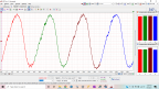
Pins 1, 2 and 3 will have 0-4V 'ramps' when the PCM wants to command ignition dwell and spark. Checking for control is gonna be tough with a test light or DMM, as neither is gonna be able to detect the ramps. If you really want to 'see' the control, it'll have to be a scope.
But! You can try a 'scratch test' on the wires between the PCM and power transistor. Check out this video for the general idea:
Your Mitsu doesn't use three-wire COP's, I know, but the control system really is the same.
The power transistor charges the ignition coils based on the ramps sent from the PCM. You'll just be simulating those ramps with the test light.Basically, if you can backprobe the PCM wire at the power transistor that correlates to the coil that isn't firing, and use the test light to make the coil fire, then you know the power transistor is working. Repeat the same test at the PCM connector. If you can make the coil fire at the power transistor, but not at the PCM, then there's a wiring problem.
That test won't tell you if there's control or not, but it WILL tell you wiring integrity and the health of the power transistor. Making sense? Ask questions as needed!
Please Log in or Create an account to join the conversation.
- shepherdguy
-
Topic Author
- Offline
- New Member
-
- Posts: 18
- Thank you received: 0
Thanks for your help!
Please Log in or Create an account to join the conversation.
- Tyler
-
- Offline
- Moderator
-
- Full time HACK since 2012
- Posts: 6115
- Thank you received: 1539
Exactly.
As long as it's the 3/6 ignition coil that isn't firing, as that's the coil associated with pin 1 at the Power Transistor.Don't touch the test light on it for terribly long, just quick taps. And have some kind of air gap set up at the coil so you can know if it's working or not.
I have been busy with Confined Space Rescue Training and drills but now have a chance to look at the car again.
No problem! That sounds... fun? :silly: Don't be training too hard.
Please Log in or Create an account to join the conversation.
- shepherdguy
-
Topic Author
- Offline
- New Member
-
- Posts: 18
- Thank you received: 0
Please Log in or Create an account to join the conversation.