2009 Chevy Traverse AWD 3.6 P0335
- CCordell
-
 Topic Author
- Offline
- Junior Member
-

- Posts: 26
- Thank you received: 3
Im Cris, I appreciate anyone taking the time reading this!! There's a long story behind this vehicle. lol I bought it then they had codes p0016, timing codes, so I decided to replace timing components. The chains, tensioners, guides, oil pumps, water pump, camshaft phasers, crank and camshaft sensors, camshaft phasers solenoid's. Then i ended up replacing the catalytic converters. it ran for awhile, then it started to have miss on cylinders 2,4,6. so I decided to redo the timing again, thinking I messed up was a tooth off in timing causing the misfiring. It ran but still the miss fire 2,4,6!
I decided to replace the throttle body, and new Maf sensor, then I used snap on verus pro to reprogram the throttle body. thinking it would fix the missing on 2, 4,6. didn't work. so latter was running it and it died. wouldn't start. then ran the codes & P0335 crankshaft position sensor signal. So I checked for 5 volts on the gray wire, it had 5 volts there. so I decided to but a new crank sensor and put it in. didn't work. I was at my friends shop had the key on, decided to wiggle the crank shaft sensor wire, and noticed it would kick the fuel pump on & off when I wiggled the wires. Then I decided to buy a new crankshaft plug end, and I rewired it in, using solder and heat shrink, but messed up with the wiring! I wired the gray 5 volt & the tan low reference wire back words. I also choose to buy a EMC with the new updated software, thinking it would solve the problem with the misfires. but it didn't fix it. I put the new computer in before wiring the crankshaft plug wrong. I don't know if runt the computer after wiring the crankshaft plug wires wrong?
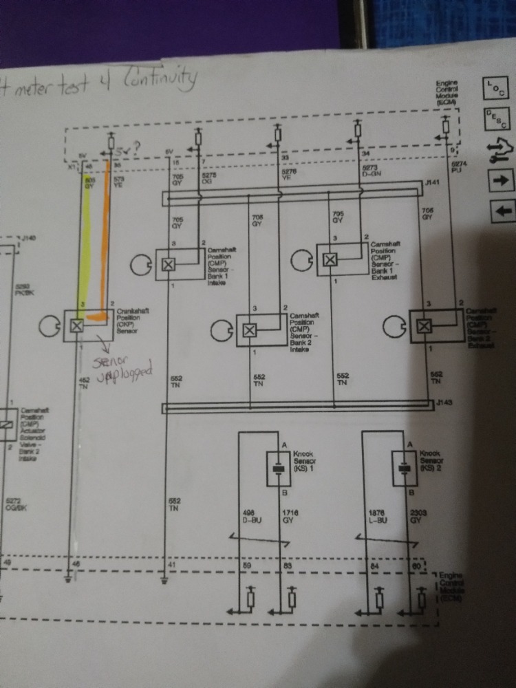
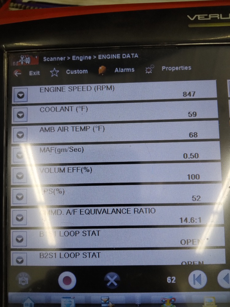
I tried to figure it out!! It would run fire a little, then die right away! & code p0335, at one time I did get p0336. but p0335 know. I have a couple off pics to put with this. It show or explains the thinks I did & results, and then the wiring diagram. I checked for continuity after rewiring the crank wires after I did it wrong. then I used scanner to verify each wire had continuity at the crank plug to related pin on back of computer. they all had continuity. The pin 3 on the crankshaft senor gray wire had 5Vts, the tan wire at crank sensor to ground had 0.01vlts. I used the scope turned on the key with crank senor plugged in & put metal behind it. thinking if I did that. On the scanner the 5volt signal would drop to zero every time I put metal under crank sensor. It didn't drop down to 0vlts, so I thought I burnt up the crankshaft position sensor I put in when I wired it wrong. Then I bought another crankshaft sensor thinking it would solve the problem? Hope I didn't damage the computer some how wiring the crankshaft sensor wire!!
The pics are a list of the things I did the other day to try to figure p0335 code & fix it, and the other one is pic of the wiring for the crankshaft sensor. I'm not sure what to do next after everything I've done!! The last thing I found out is that I took the crankshaft position sensor off, then I check for voltage at back of the computer on pin 35 signal wire. and my scanner said there was 5vlts there at the computer with crank sensor off??? I not 100% sure if its suppose to read 5vlts there on pin 35 with sensor disconnected??? think or wondering if some where some how the 5volt gray wire is toughing the yellow wire some wear in the wiring harness causing this, or the 5 volts suppose to be there with sensor off? I don't know!! I'm new to figuring stuff like this out!! I hate wiring problem!! LOL I'm not sure what my next move is.
Thank you for your time reading this! I appreciate it and any advise with this wonderful traverse. LOL

Please Log in or Create an account to join the conversation.
- juergen.scholl
-

- Offline
- Platinum Member
-

- Active partschanger
- Posts: 1230
- Thank you received: 462
There also may be bias voltage present, though typically this is not 5 V but a different voltage level.
You may want to disconnect the harness from the sensor and from the pcm as well and check then for a short/continuity between the grey and yellow wires.
An expert is someone who knows each time more on each time less, until he finally knows absolutely everything about absolutely nothing.
Please Log in or Create an account to join the conversation.
- CCordell
-
Topic Author
- Offline
- Junior Member
-
- Posts: 26
- Thank you received: 3
I know I tried to test the new crank sensor. I plugged it in, then the key on, I put tee pin on the back of the computer on pin 35, crankshaft signal wire, the scope said 5vlts. I put a piece of metal under the crk sensor to see if the volt would drop to zero, and it didn't! IT confused me because it was doing the same thing as the older crank sensor I just had in??? I believe the computer uses the low reference wire to create a square wave, drop the voltage to zero.
thanks for reading this!! I don't now if anyone has any more ideas, or suggestions on what to do or check next. Thanks!!! Appreciate your time & information a lot!!!!!
Please Log in or Create an account to join the conversation.
- CCordell
-
Topic Author
- Offline
- Junior Member
-
- Posts: 26
- Thank you received: 3
I know there's continuity on all 3 wires. Gray wire at the crk sensor has 5vlts at the sensor with key on, the pin 1 low reference wire has 0.01 vlts from ground There is 5vlts when I jump across the pin 3 5vlts supple and touch the pin 1 low reference wire at the crank sensor wire key on. At pin 2 signal wire at sensor there is 5vlts present when I touch good ground,
thanks for your time reading this!! Appreciate it a lot!! Have a great Day!!!!!
Please Log in or Create an account to join the conversation.
- juergen.scholl
-
- Offline
- Platinum Member
-
- Active partschanger
- Posts: 1230
- Thank you received: 462
The signal will be seen on what's called the signal wire, not on the low ref one. Yes, the V ref and the low ref wires are needed to make this hall effect sensor toggle the signal between 5 and 0 volts but the signal/square wave will show up up on the signal wire only, not on the low ref one.
Again, do you get a square wave when cranking the engine?
(Just putting a piece of metal to the sensor tip may not be enough to test the sensor accurately, you would have to move it close to and away from the tip continously in order to simulate a signal.)
An expert is someone who knows each time more on each time less, until he finally knows absolutely everything about absolutely nothing.
Please Log in or Create an account to join the conversation.
- juergen.scholl
-
- Offline
- Platinum Member
-
- Active partschanger
- Posts: 1230
- Thank you received: 462
An expert is someone who knows each time more on each time less, until he finally knows absolutely everything about absolutely nothing.
Please Log in or Create an account to join the conversation.
- CCordell
-
Topic Author
- Offline
- Junior Member
-
- Posts: 26
- Thank you received: 3
Have great day!!!
Please Log in or Create an account to join the conversation.
- CCordell
-
Topic Author
- Offline
- Junior Member
-
- Posts: 26
- Thank you received: 3
Thanks for your information!! I was curious about hooking up the cables to the scope the right way for reading the crank sensor? I know I hook up the yellow wire to back of computer on pin 35 where the crk sensor signal wire is, but not 100% sure witch way to put the black wire ground for scope? Do I put it on a good know ground or put it on the low reference wire pin 46 low reference on back of computer. So I know its hooked up right. see what the scope says when I turn it over.
Thanks for your time!! and information!!
Please Log in or Create an account to join the conversation.
- juergen.scholl
-
- Offline
- Platinum Member
-
- Active partschanger
- Posts: 1230
- Thank you received: 462
Nevertheless when looking at only one channel at a time you could use the low ref to connect the ground wire to .
An expert is someone who knows each time more on each time less, until he finally knows absolutely everything about absolutely nothing.
Please Log in or Create an account to join the conversation.
- CCordell
-
Topic Author
- Offline
- Junior Member
-
- Posts: 26
- Thank you received: 3
. I used a common ground. & I got 5 volts when key on at pin 35 at computer. I cranked it then rerun the video, & the voltage didn't drop down at all cranking.
I used pin 46 low reference on back of computer. I didn't get 5 volts when turn key on! The scope reading were goofy!! Volts jumped up & down 80 to negative -40???
I had my common ground at on time off & didn't now it & it was doing the same thing on scope? Plugged the ground back on got 5 volts.
Maybe I'm not getting a good ground from 4 the pin 46 low reference wire from crk sensor??
Maybe I need to run all new 3 wire from the crank to computer?? I'm not sure what to do next!! Key on 5vlts at computer on crk signal. But when crank it doesn't drop down to zero? Could there be a problem with computer now? I have the old one! I have the new program pcm in know.
Thanks for reading, & your help is appreciated a lot!!
Please Log in or Create an account to join the conversation.
- juergen.scholl
-
- Offline
- Platinum Member
-
- Active partschanger
- Posts: 1230
- Thank you received: 462
Make sure/double-check all wires are in the correct plug terminals, eg tan wire at sensor plug #1 and pcm #46, sensor plug #2 yellow wire to #35 at pcm and finally #3. at sensor plug (grey wire) to pcm #45.
Verify the corresponding voltage levels with koeo..
Check for a crank signal while cranking. If not present try to simulate one pulsing the signal wire to ground with a test light and looking for rpm pid in scan data (also, does the fuel pump kick in?)
If you don't get any rpm that way then doublcheck the yellow signal wire makes it to the pcm. If it does then you're looking at a pcm issue.
If there is an rpm signal while pulsing the sensor make sure the reference voltage on pin 3 does not disappear while cranking (with the sensor plugged in). If no problem with Vref then verify low ref, again while cranking. If any doubt jumper the tan wire from pin #1 directly to a good ground.
If the above tests turn out ok and there is still no signal/rpm reading while cranking make sure the reluctor is actually spinning and the sensor actually is not broken.
Report back from there.
An expert is someone who knows each time more on each time less, until he finally knows absolutely everything about absolutely nothing.
Please Log in or Create an account to join the conversation.
- CCordell
-
Topic Author
- Offline
- Junior Member
-
- Posts: 26
- Thank you received: 3
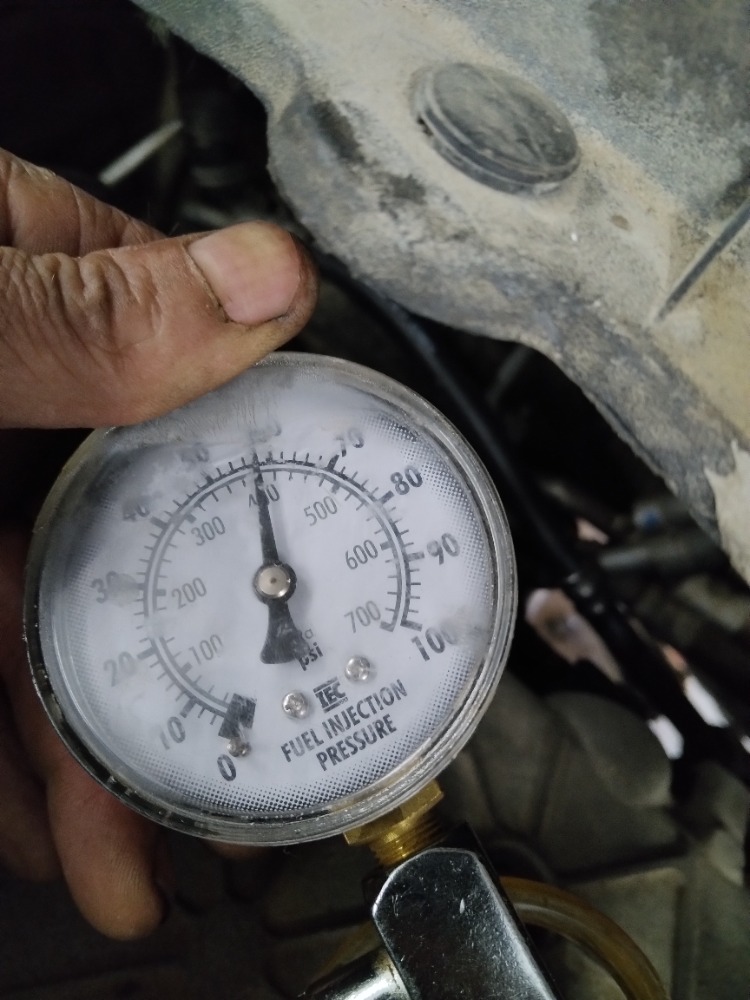
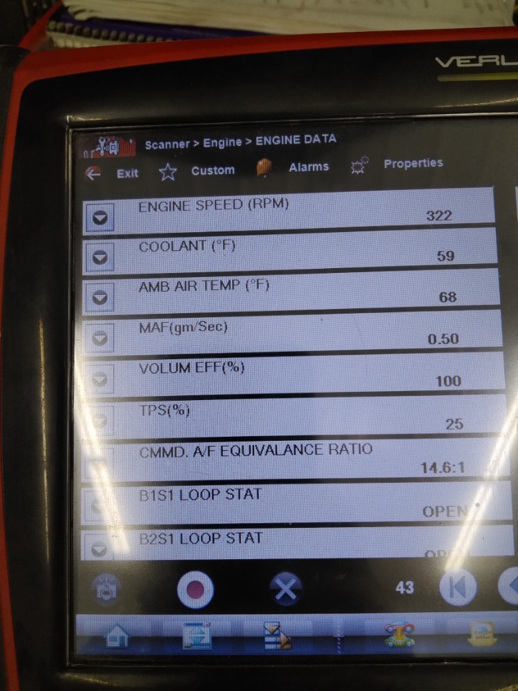
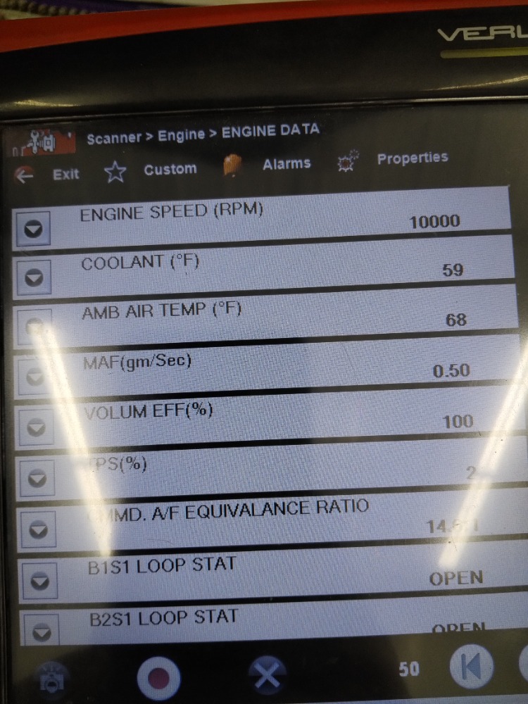
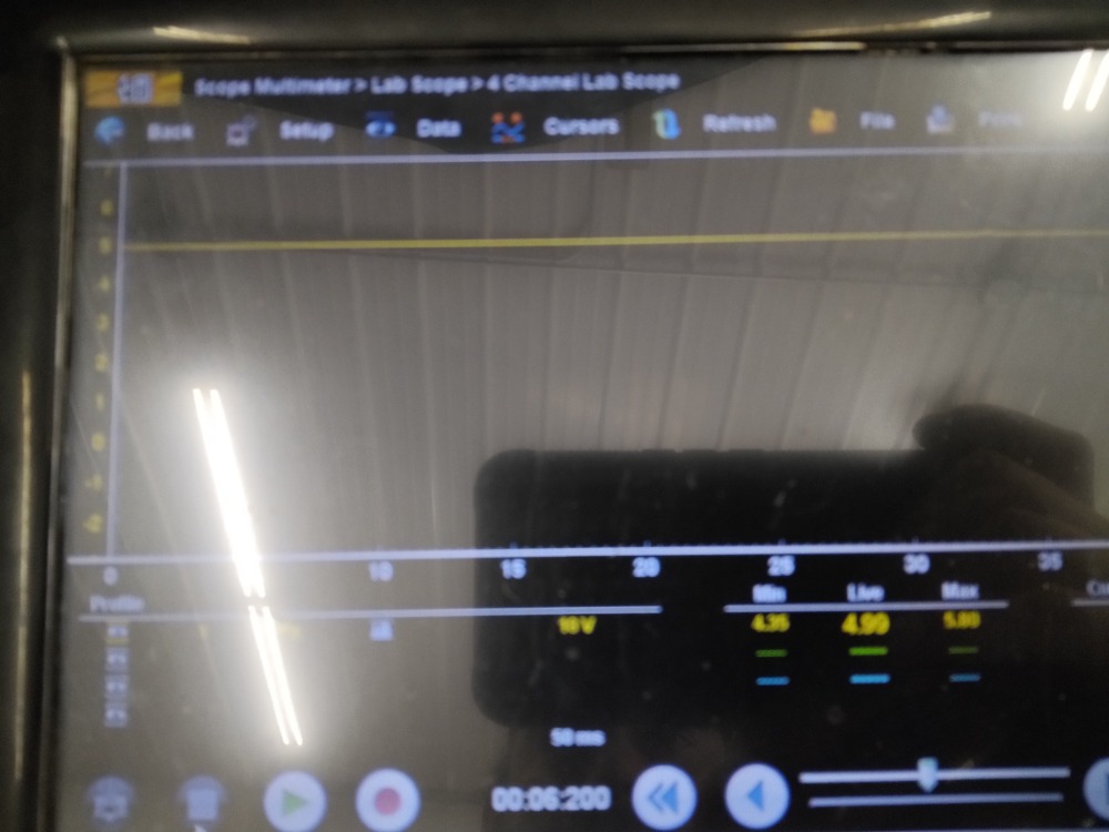
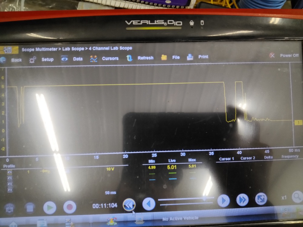
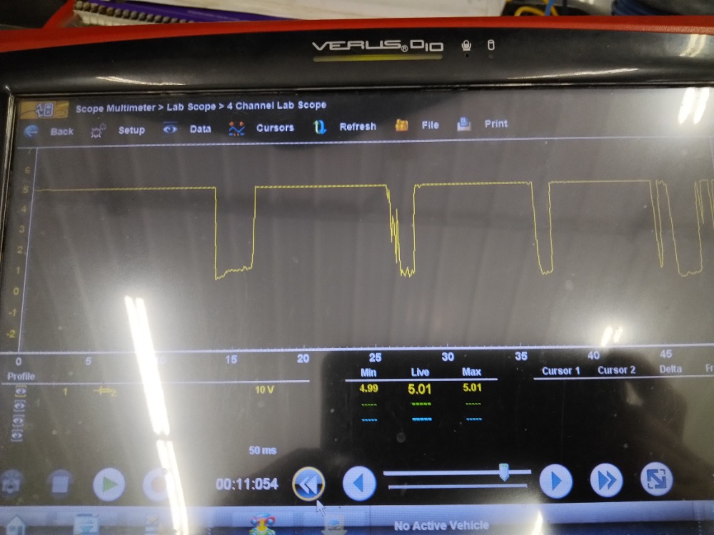
Thanks 4 your information! I appreciate it a lot!! The fuel pump kick on when I turn the key. 60psi. I used the scope & used the test light to simulate a pulse,when I touched the crk signal wire at the computer it created a wave & dropped down to zero like it's suppose to. Then I checked the rpm reading , & it showed rpm when I used the test light touched the signal wire crk at the back of computer.
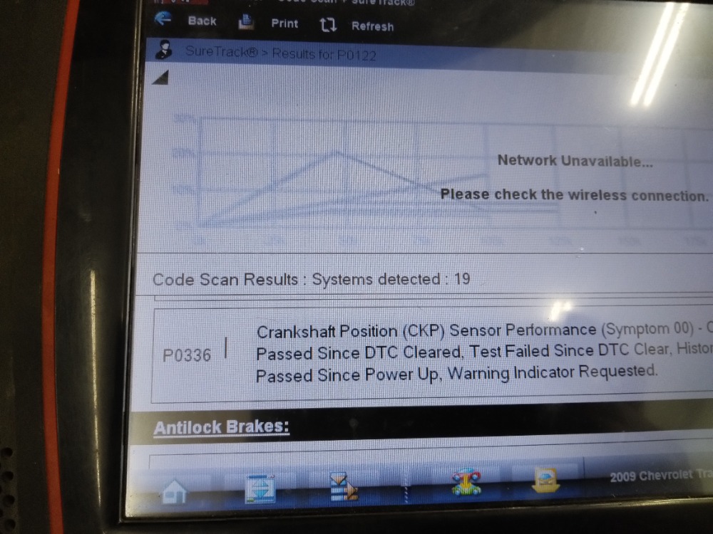
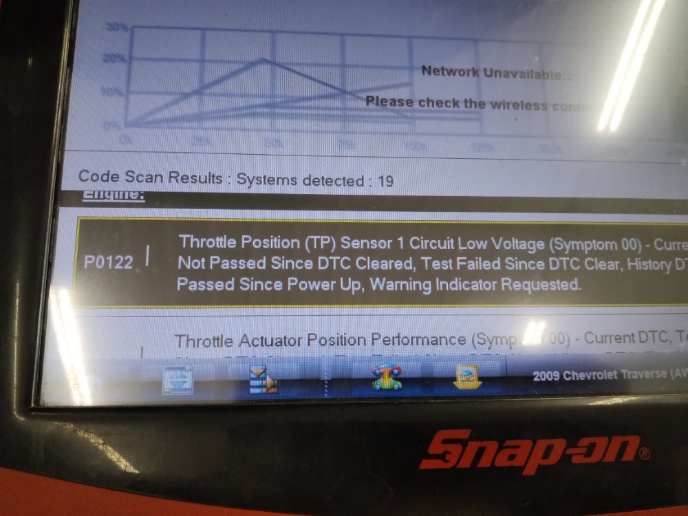
I tried cranking it, when I cranked engine the scope stayed at 5vlts. I have pictures to show u. Had the battery disconnect to charge it. Before even cranking engine. I received codes? Just by touching the crank signal by computer. P0336 crank position sensor performance, then
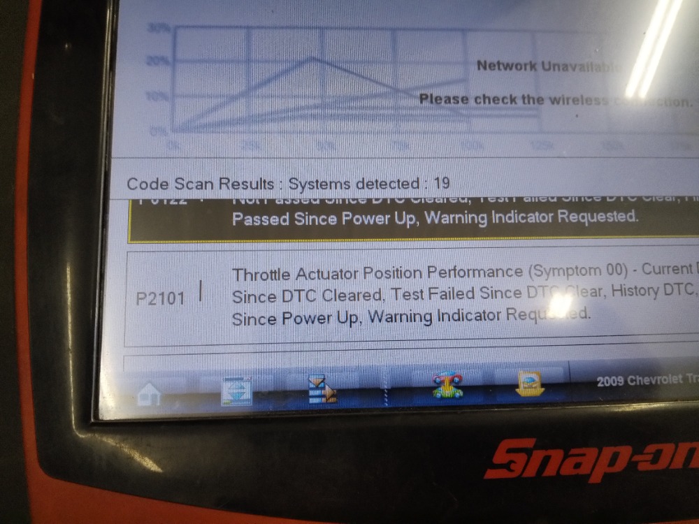
P0122 throttle position sensor circuit low voltage
P2101 throttle actuator position performance
P0335 crank position circuit not pass test
Maybe I caused the codes when I was grounding the crank signal at computer? I now I heard the throttle move.
I'll send pics with to show what happened.
Thanks 4 all ur help!! It really appreciate a lot!! Please let me know what u think about what u see with the pics & about the results with things I've done already & suggestions on next step.
Thank you so much!!
Please Log in or Create an account to join the conversation.
- ernest.cordwell
-
- Offline
- New Member
-

- Posts: 1
- Thank you received: 0
Please Log in or Create an account to join the conversation.