2004Ford e450 FPDM diagnostics and wiring question
- hard.wired
-
 Topic Author
- Offline
- New Member
-

- Posts: 9
- Thank you received: 0
1. Fuel pump power = 12.1v KOEO and 10.65 cranking
2. Fuel pump ground = 12.1v KOEO and 10.62 cranking
3. FPDM power from IFS = 12.0v KOEO and 10.6v cranking
4. FPDM ground = 3.75 KOEO and 6.7v cranking
How would one interpret these results?
Here is a picture of the wiring by the FPDM which I have removed some of the electrical tape to look at the grounds. Is it common to have the wiring look as such, looks kind of funky to me. The FPDM is mounted on a plate coming off of the frame, so I am wondering if this is causing some problem with ground. Also, the wiring diagram is below and shows a twisted pair of wires, I think fuel pump power and ground. These I believe were wrapped with electrical tape that had some sort of foil underneath. Is this common as well? This thread is a follow-up to an earlier thread. I had different results the other day..everything checked out okay, but had FPDM ground = 0v KOEO and 2-4v cranking. Not sure where to go from here??


Please Log in or Create an account to join the conversation.
- Tyler
-
- Offline
- Moderator
-

- Full time HACK since 2012
- Posts: 6124
- Thank you received: 1541
Just to be perfectly clear, these measurements were taken when the van wasn't starting, right? Are these the pins at the FPDM that you were testing?
1. Fuel pump power = 12.1v KOEO and 10.65 cranking Pin 4
2. Fuel pump ground = 12.1v KOEO and 10.62 cranking Pin 2
3. FPDM power from IFS = 12.0v KOEO and 10.6v cranking Pin 5
4. FPDM ground = 3.75 KOEO and 6.7v cranking Pin 3
First thing I see is the pump not getting run, since the ground voltage never changes from system voltage. Second is the elevated ground voltage on Pin 3, waaaaaay too high. I can see why you were interested in looking at the grounds! :lol:
You're right on about the twisted pair of wires for the pump, and it looks like the shield for the pump motor and level sender ends up grounding in the same location as the FPDM. That splice in your picture looks OE to me - that may actually be S312 in the diagram.
Anyway, I think you've found the problem with the FPDM ground.
 Just to test that theory, you could backprobe that pin and add a jumper wire from B-. With a good ground, the module should work correctly. If it does, then pursue a high resistance problem on the FPDM ground.
 Please Log in or Create an account to join the conversation.
- hard.wired
-
Topic Author
- Offline
- New Member
-
- Posts: 9
- Thank you received: 0
Tyler wrote: Just to be perfectly clear, these measurements were taken when the van wasn't starting, right? Are these the pins at the FPDM that you were testing?
No worries on the delay, I am glad to get help on this! Yes, I am currently at a crank/no start condition. And yes, those are the correct pins that were tested.
Tyler wrote: You're right on about the twisted pair of wires for the pump, and it looks like the shield for the pump motor and level sender ends up grounding in the same location as the FPDM. That splice in your picture looks OE to me - that may actually be S312 in the diagram.
Anyway, I think you've found the problem with the FPDM ground.
Do I need to re-wrap that twisted pair with some sort of foil tape? I like the idea of jumpering from battery ground. I'll give this a try and report back.
Please Log in or Create an account to join the conversation.
- Tyler
-
- Offline
- Moderator
-
- Full time HACK since 2012
- Posts: 6124
- Thank you received: 1541
hard.wired wrote: No worries on the delay, I am glad to get help on this! Yes, I am currently at a crank/no start condition. And yes, those are the correct pins that were tested.
OK, gotcha. Correct me if I'm wrong, but wasn't this an intermittent no start before? Has it graduated to a complete no start?
Do I need to re-wrap that twisted pair with some sort of foil tape?
Eh, probably should, but I dunno where you'd get the foil tape. :lol: How much of it did you remove? If it was just an inch or two, I'd just use regular electrical tape and call it good.
Please Log in or Create an account to join the conversation.
- hard.wired
-
Topic Author
- Offline
- New Member
-
- Posts: 9
- Thank you received: 0
Tyler wrote: OK, gotcha. Correct me if I'm wrong, but wasn't this an intermittent no start before? Has it graduated to a complete no start?
Yes, it was intermittent before and now complete no start. However, the test that you suggested worked well! I jumpered from battery negative straight to FPDM ground and fuel pump ground. The engine started right up. Here are the results for the two tests I did with that set-up:
1. FPDM ground = 0 volts KOEO and near 0 volts KOER
2. Fuel pump ground = battery voltage at KOEO and 7.4 v at KOER
Shouldn't this circuit be getting near 0 volts (full ground) while cranking and engine running?
Please Log in or Create an account to join the conversation.
- Tyler
-
- Offline
- Moderator
-
- Full time HACK since 2012
- Posts: 6124
- Thank you received: 1541
hard.wired wrote: However, the test that you suggested worked well! I jumpered from battery negative straight to FPDM ground and fuel pump ground. The engine started right up.
Nice.
")
Now you get the pleasure of tracking the bad ground. :lol: OR, you can make the redundant ground a permanent thing, if you're not interested in chasing wires.
Shouldn't this circuit be getting near 0 volts (full ground) while cranking and engine running?
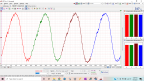
You'd think so! But that's what makes the FPDM different from most setups - it almost never gives the pump a steady ground, even during cranking. Here's a cleaned up version of the known good captures I posted in the first thread:

Green is pump power, yellow is pump ground. Cursor one marks when the pump starts running, and cursor two marks when the engine actually started. The FPDM grounds the pump pretty heavily at times, but never constantly. This is why your DVOM is showing you around 7V.
Please Log in or Create an account to join the conversation.
- hard.wired
-
Topic Author
- Offline
- New Member
-
- Posts: 9
- Thank you received: 0
Tyler wrote:
Now you get the pleasure of tracking the bad ground. :lol: OR, you can make the redundant ground a permanent thing, if you're not interested in chasing wires.
I actually like the idea of making a permanent ground for the FPDM/fuel pump ground. This will ensure that there is a good clean ground and won't have to worry about integrity of grounding straps and such. I will still investigate the frame grounding on that side of the vehicle. Might be that the FPDM mounting plate is less than ideal for ground.
Tyler wrote:
Here's a cleaned up version of the known good captures I posted in the first thread:
Green is pump power, yellow is pump ground. Cursor one marks when the pump starts running, and cursor two marks when the engine actually started. The FPDM grounds the pump pretty heavily at times, but never constantly. This is why your DVOM is showing you around 7V.
Thanks for this. These known good plots seem really useful, especially for referencing after you have made potential fixes. I will go ahead and make a dedicated ground, tape up my wiring and report back. Hopefully p1233 will go away for good! Many thanks for all the insight!
Please Log in or Create an account to join the conversation.
- Tyler
-
- Offline
- Moderator
-
- Full time HACK since 2012
- Posts: 6124
- Thank you received: 1541
The P1237 may be due to the ground problem screwing with the FPDM internal performance and diagnostics. A bit misleading, initially. In retrospect, I think the P1233 is the code to follow in cases like this.
Please Log in or Create an account to join the conversation.