
.256mV Alternator A/C ripple
- DGB
-
 Topic Author
- Offline
- New Member
-

- Posts: 17
- Thank you received: 0
Please Log in or Create an account to join the conversation.
- Tyler
-
- Away
- Moderator
-

- Full time HACK since 2012
- Posts: 6146
- Thank you received: 1551
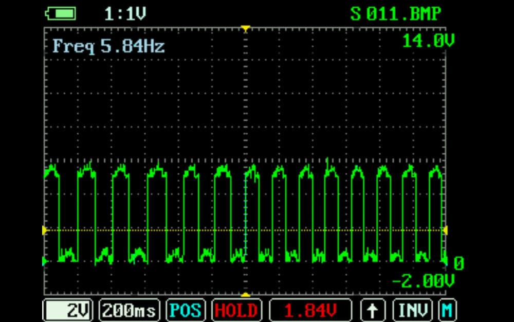
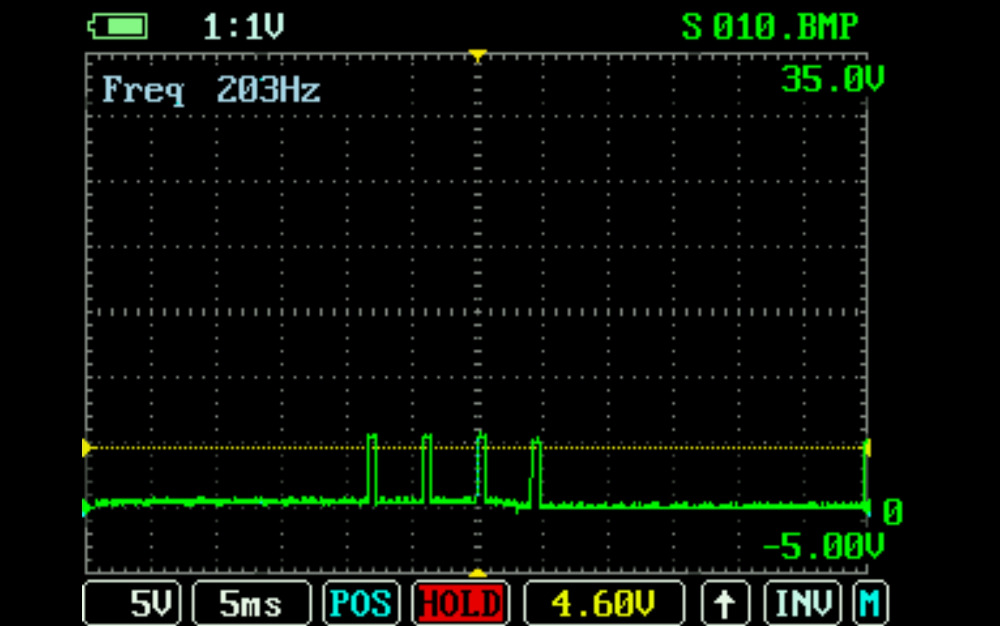
I don't blame you at all for suspecting the PCM, but I'd want to have another look at the cam/crank before pulling the trigger on a replacement. Would you mind posting the waveforms?
Please Log in or Create an account to join the conversation.
- DGB
-
Topic Author
- Offline
- New Member
-
- Posts: 17
- Thank you received: 0
Please Log in or Create an account to join the conversation.
- DGB
-
Topic Author
- Offline
- New Member
-
- Posts: 17
- Thank you received: 0
Please Log in or Create an account to join the conversation.
- DGB
-
Topic Author
- Offline
- New Member
-
- Posts: 17
- Thank you received: 0
Please Log in or Create an account to join the conversation.
- Chad
-

- Offline
- Moderator
-
- I am not a parts changer.
- Posts: 2219
- Thank you received: 743
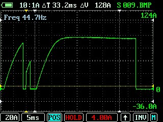
Scope at 10:1 ignition preset
This is why your reading such high amperage. The scope is multiplying the signal by 10x. You do not need this setting with an amp clamp.
This setting is for when you are using an attenuator to reduce voltage input to the scope, like you would when capturing a Coil Primary Voltage waveform.
"Knowledge is a weapon. Arm yourself, well, before going to do battle."
"Understanding a question is half an answer."
I have learned more by being wrong, than I have by being right.

Please Log in or Create an account to join the conversation.
- DGB
-
Topic Author
- Offline
- New Member
-
- Posts: 17
- Thank you received: 0
Please Log in or Create an account to join the conversation.
- Chad
-
- Offline
- Moderator
-
- I am not a parts changer.
- Posts: 2219
- Thank you received: 743
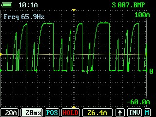
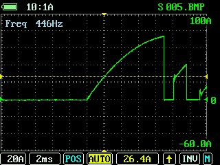
It looks like the coil is charging up and saturating but failing to be pulled down consistently, or am I reading it wrong?
To see if it is "pulling down", consistently, capture a Primary Voltage waveform. Swap out your amp probe for test leads. Negative lead to BAT (-). Positive lead to the Coil control wire.
When the coil is not energized, you should see battery voltage on the control wire. When the PCM energizes the coil, the voltage on the control wire will be pulled down to zero. When the PCM De-energizes the coil, there will be a voltage spike on the control wire that could reach 400 volts. This is where you need 10:1 attenuation because the maximum voltage input of the uScope is 40 volts. An attenuator is used to reduce the 400 volts down to 40 volts before it enters the scope. To account for this, the 10:1 setting on the scope will multiply the input voltage by 10 and display the proper, original, voltage output on the screen.
Are your Coil Current waveforms captured with the engine running, engine cranking, or energizing the coil manually? Because I agree with Tyler. 30+ ms dwell time is crazy.

"Knowledge is a weapon. Arm yourself, well, before going to do battle."
"Understanding a question is half an answer."
I have learned more by being wrong, than I have by being right.
Please Log in or Create an account to join the conversation.
- DGB
-
Topic Author
- Offline
- New Member
-
- Posts: 17
- Thank you received: 0
Please Log in or Create an account to join the conversation.
- DGB
-
Topic Author
- Offline
- New Member
-
- Posts: 17
- Thank you received: 0
Please Log in or Create an account to join the conversation.
- DGB
-
Topic Author
- Offline
- New Member
-
- Posts: 17
- Thank you received: 0
Please Log in or Create an account to join the conversation.
- Chad
-
- Offline
- Moderator
-
- I am not a parts changer.
- Posts: 2219
- Thank you received: 743
I would not consider anything less than 300 mV, 0.3 V, to be a problem.
300-500 mV would start to get my attention, only, if I was chasing electrical anomalies, But I would not be real concerned until 500 mV, or more.
"Knowledge is a weapon. Arm yourself, well, before going to do battle."
"Understanding a question is half an answer."
I have learned more by being wrong, than I have by being right.
Please Log in or Create an account to join the conversation.
- DGB
-
Topic Author
- Offline
- New Member
-
- Posts: 17
- Thank you received: 0
Please Log in or Create an account to join the conversation.
- Chad
-
- Offline
- Moderator
-
- I am not a parts changer.
- Posts: 2219
- Thank you received: 743
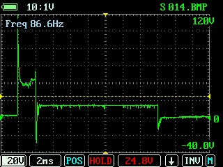
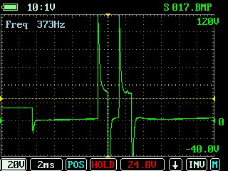
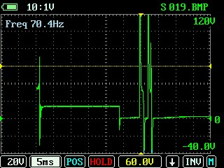
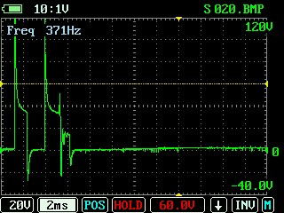
Excessive AC Ripple will, absolutely, affect a 2-wire VR type sensor. However, this crank sensor is a 3-wire hall effect sensor, and I am not very confident that a ripple of less than 300 mV could be your problem. I suppose, you could fully charge the battery and disconnect the alternator for comparison.I do believe I have some sort of electronic anomalie... I am also getting a crazy RPM signal on my scan tool that does not reflect what the actual tach is reading.
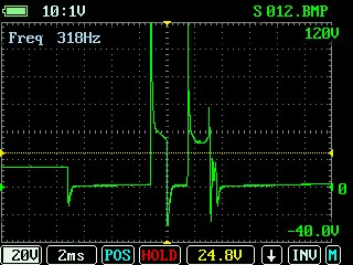
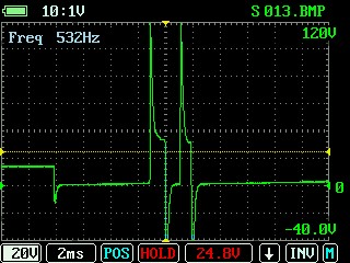
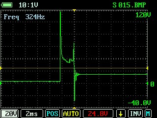
Here are the screen shots from the new test. Primary coil control back probed. Engine at idle. The shots showing 2 wave forms back to back, is that something I am doing wrong with the scope? none the less these don't look good
Base on those Primary Voltage waveforms, I would pull the spark plugs to make sure they are not fouled.
But, the thing that concerns me the most is the back-to-back firing events. It will be impossible to do with a single channel scope, but I would like to see a waveform of Cam, Crank, Coil control, and #1 injector control, all at once.
"Knowledge is a weapon. Arm yourself, well, before going to do battle."
"Understanding a question is half an answer."
I have learned more by being wrong, than I have by being right.
Please Log in or Create an account to join the conversation.
- DGB
-
Topic Author
- Offline
- New Member
-
- Posts: 17
- Thank you received: 0
Please Log in or Create an account to join the conversation.
- Chad
-
- Offline
- Moderator
-
- I am not a parts changer.
- Posts: 2219
- Thank you received: 743
Good eye! If you had a 2-channel scope, I bet the current waveform would show these areas as some crazy-long dwell times. I think that I would disconnect the coil control wire from the Coil and PCM. A continuity to ground check with an Ohm meter should display OL. Give the wiring harness a good wiggle and watch the Ohm meter for any continuity to ground. If no faults are found with the control wire, I would begin to suspect a faulty PCM. However, I would still want to see Cam/Crank and coil and injector controls, all together.What caught my eye is on some of these snap shots the voltage is not coming back up to 14V after coil discharge like the very last screen shot (S015.bmp) which looks like it should.
"Knowledge is a weapon. Arm yourself, well, before going to do battle."
"Understanding a question is half an answer."
I have learned more by being wrong, than I have by being right.
Please Log in or Create an account to join the conversation.
- DGB
-
Topic Author
- Offline
- New Member
-
- Posts: 17
- Thank you received: 0
Please Log in or Create an account to join the conversation.
- DGB
-
Topic Author
- Offline
- New Member
-
- Posts: 17
- Thank you received: 0
Please Log in or Create an account to join the conversation.
- DGB
-
Topic Author
- Offline
- New Member
-
- Posts: 17
- Thank you received: 0
Please Log in or Create an account to join the conversation.
- Tyler
-
- Away
- Moderator
-
- Full time HACK since 2012
- Posts: 6146
- Thank you received: 1551
I didn't think of it before. Voltage drop on that coil control wire, no telling how long it has been that way. Could have stressed the driver?
Excessive voltage drop generally won't cause driver damage, as voltage drop will cause less current flow, not more. Less current flow, less heat.
I agree with Chad, we really need to see the cam and crank together. It also kinda looks like the CMP signal voltage is changing when it shouldn't be. The 5V and ground sections both have regular 'peaks'. Those might get misinterpreted by the PCM as a signal transition.
Please Log in or Create an account to join the conversation.