A place to discuss hardware/software and diagnostic procedures
Secondary ignition waveform/scope question
- Smothers1690
-
 Topic Author
- Offline
- New Member
-

Less
More
- Posts: 1
- Thank you received: 0
8 years 9 months ago - 8 years 9 months ago #10725
by Smothers1690
Secondary ignition waveform/scope question was created by Smothers1690
So I have watched a bunch of scannerdanner videos as well as a few others about oscilloscopes and their uses. I recently decided to purchase a scope(hantek 1008c) after buying a uscope( which I think was a knockoff made by airtex?). I didn't really like the uscope. I didn't like the single channel and I had trouble getting decent waveforms.
I work on forklifts and a lot of the trucks I work on have distributors. I have been able to get some waveforms on the few trucks I've tried that have dis systems. but I'm having some issues that I had on the uscope and still having on the hantek
Both issues happen when using the ignition pickup probe that came with scope. I clip the probe around a spark plug wire and the negative lead on chassis ground.
First off the waveform is upside down from the beginning. I can invert the image but the trigger doesnt invert if that makes sense. So basically even though the image is inverted I still have to drag the trigger downward in order to move it toward "higher" voltage.
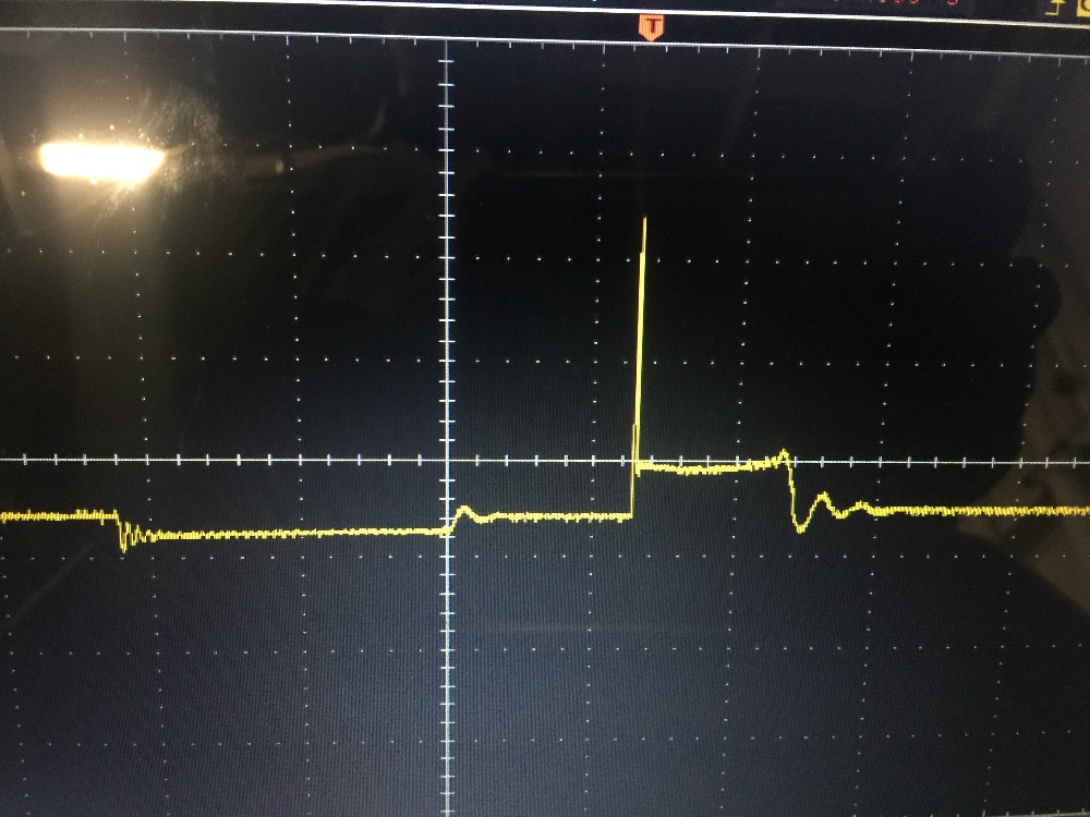
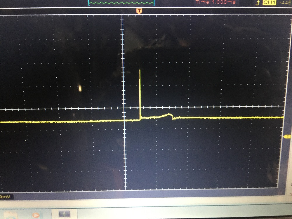
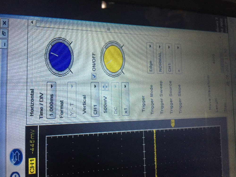
Second problem I have is the waveforms on the plug wires have very little detail. If I attach the lead to the coil wire I get very good waveforms.I attached images below. 1st is when hooked up to ignition cool wire. 2nd pic is when hooked to plug wire and 3rd pic is the setting.
any help with these issues would be appreciated. I originally chalked it up to the uscope(or knockoff) I bought being junk but the fact that both scopes are found the same thing makes me think I'm doing something wrong. Thanks in advance.
I work on forklifts and a lot of the trucks I work on have distributors. I have been able to get some waveforms on the few trucks I've tried that have dis systems. but I'm having some issues that I had on the uscope and still having on the hantek
Both issues happen when using the ignition pickup probe that came with scope. I clip the probe around a spark plug wire and the negative lead on chassis ground.
First off the waveform is upside down from the beginning. I can invert the image but the trigger doesnt invert if that makes sense. So basically even though the image is inverted I still have to drag the trigger downward in order to move it toward "higher" voltage.
Second problem I have is the waveforms on the plug wires have very little detail. If I attach the lead to the coil wire I get very good waveforms.I attached images below. 1st is when hooked up to ignition cool wire. 2nd pic is when hooked to plug wire and 3rd pic is the setting.
any help with these issues would be appreciated. I originally chalked it up to the uscope(or knockoff) I bought being junk but the fact that both scopes are found the same thing makes me think I'm doing something wrong. Thanks in advance.
Last edit: 8 years 9 months ago by Smothers1690.
Please Log in or Create an account to join the conversation.
- Andy.MacFadyen
-

- Offline
- Moderator
-

Less
More
- Posts: 3357
- Thank you received: 1037
8 years 9 months ago - 8 years 9 months ago #10736
by Andy.MacFadyen
" We're trying to plug a hole in the universe, what are you doing ?. "
(Walter Bishop Fringe TV show)
Replied by Andy.MacFadyen on topic Secondary ignition waveform/scope question
Hantek fall down badly on the software, the most basic Hantek model won't even invert the signal.
Actually the ignition captures are pretty good and what you can expect with a DIS system. On a DIS there are two gaps the spark must jump , the spark has to jump the gap between the rotor arm and the cap before it reaches the spark plug. Because of the the pattern will look different depending on where the dIS probe is attached.
If you look at the voltage on the coil wire (aka centre lead or "king lead") you are going to see the primary voltage before during and after the spark jumps. But if the probe is clipped to an individual plug wire you will only see voltage while the spark is actually jumping so you won't see detail in of the voltage build up and any coil "ringing".
With a DIS when using the probe on the coil wire it is really a case of looking for any firing event that looks different from the other cylinders, you are looking at the forrest not the leaves on each tree. Only when you attach to the coil wire, you can see all the detail of before and after the spark jumps.
There are so many different ignition system in use that nothing is written in stone so it is really a case of learning what is normal for a particular engine type.
The poblem you had with lack of detail on the uScope clone (DSO201 Nano?) I don't know what firmware was on your scope (better ones are "Paul's" or "Ben-F" ) but I believe was actually at least partly due to a menu setting, On boot up the scope defaults to a slow sample speed, to get any detail fast sample rate must be selected and this menu option is not obvious.
" We're trying to plug a hole in the universe, what are you doing ?. "
(Walter Bishop Fringe TV show)
Last edit: 8 years 9 months ago by Andy.MacFadyen.
Please Log in or Create an account to join the conversation.
Time to create page: 0.305 seconds