Volkswagen 1.6i strange problem - Fixed
- Ash03
-
 Topic Author
- Offline
- Premium Member
-

- Posts: 147
- Thank you received: 6
This car has a 8 pin TPS with a built in idle control stepper motor, 4 pin map sensor with a built in air temp sensor, 4 pin water temp sensor, 3 pin distributor and a 3 pin knock sensor. IT DOES NOT HAVE A CRANK AND CAM POSITION SENSOR.
The car came in with a bearing knock, fluctuating idle and a bad over fueling issue.
Before stripping the engine apart I scanned for dtcs and I found 2 Codes
1. Map sensor short to positive
2. Air intake temp sensor short to positive
I cleared the codes. Overhauled the engine. Started the car up again with the same sensor and I got the same dtcs and symptoms (fluctuating idle and over fueling)
So I unplugged the map sensor connector and did a few tests
1. Checked for 5v reference on the map and air temp wires - was good got 5.01v on both wires
2. Checked for ground - was good as well
3. Signal wire has 5v (i believe the voltage varies depending on sensor output)
So basically the wiring is OK.
I tested the sensor next. Sensors output value was the same irrespective on the vacuum applied to it (it also smells burnt) so I replaced the sensor with a new part.
After fitting on the new map sensor the car is still behaving weirdly.
The problem the car has now - it starts up and dies after a second. It cannot idle. It revs up as if starving for fuel and cannot rev unless the throttle is open wide (WOT) but it does not throw any dtcs.
If the map sensor is unplugged, the car can start and idle the same as with the damaged sensor (fluctuating and over fueling)
If the TPS is unplugged and map is plugged, the car will start rev up fine, no over fueling it just doesn't idle as the idle control is built into the TPS.
So I decided to test the TPS and it also works 100%
Now im starting to get worried as I don't know what's going on.
I then decided to get an ecu pinout and test all wires from ecu plug to the specific component that's being fed by the ecu.
All turned out 100% no open circuits or shorts in the wiring.
The car has no vacuum leaks, the timing is 100%, has proper fuel pressure.
Can somebody please help me any input will be greatly appreciated.
Please Log in or Create an account to join the conversation.
- mreyes92
-
- Offline
- New Member
-

- Posts: 1
- Thank you received: 0
Please Log in or Create an account to join the conversation.
- Doc n2mx
-
- Offline
- Senior Member
-

- Posts: 44
- Thank you received: 10
Can you give the vin and year?
you tested the wiring I was wondering just how you did this , did you use a load or just a ohm meter?
Doc N2mx
Please Log in or Create an account to join the conversation.
- Ash03
-
Topic Author
- Offline
- Premium Member
-
- Posts: 147
- Thank you received: 6
Vin AAVZZZ6KZVU008183
Sent from my SM-G531H using Tapatalk
Please Log in or Create an account to join the conversation.
- Ash03
-
Topic Author
- Offline
- Premium Member
-
- Posts: 147
- Thank you received: 6
I first checked the voltages on ref wires with the key on engine off..Doc n2mx wrote: Hi ,
Can you give the vin and year?
you tested the wiring I was wondering just how you did this , did you use a load or just a ohm meter?
Doc N2mx
Then, I tested the loom with it unplugged from the ecu and whatever sensor it went to, with an ohm meter.. the wires tested between 0.1-0.2ohms.
Is there any other way thats more effective?
I watched so many of Pauls videos that I sometime get confused lol ( Im not good with wiring)
Sent from my SM-G531H using Tapatalk
Please Log in or Create an account to join the conversation.
- Ash03
-
Topic Author
- Offline
- Premium Member
-
- Posts: 147
- Thank you received: 6
Sent from my SM-G531H using Tapatalk
Please Log in or Create an account to join the conversation.
- Andy.MacFadyen
-

- Offline
- Moderator
-

- Posts: 3357
- Thank you received: 1037
It looks like the MAP output and possibly the IAT wire from the TMAP are shorted to +5v reference the thing you have to test for is if this is in the wiring harness or inside the ECU.
Knowing VW I would suspect a harness issue. With the harness unplugged from the ECU and the TMP check the ressistance between both the IAT output and the MAP output and the 5v reference.
" We're trying to plug a hole in the universe, what are you doing ?. "
(Walter Bishop Fringe TV show)
Please Log in or Create an account to join the conversation.
- Andy.MacFadyen
-
- Offline
- Moderator
-
- Posts: 3357
- Thank you received: 1037
The TMAP sensor is simply two completely separate sensors built into the same unit, the only wire they share is a common ground.
The IAT side is a conventional thermistor with 5v supply and uses the common ground.
The MAP sensor side has a 5 supply, sensor output and also shares the common ground.
Normally with the sensor unplugged key on engine off I would expect to see roughly:
IAT wire 4.9v to 5v
MAP reference 5 to 5.1 v
MAP output pin close to 0v
Ground Pin very close to 0 volts.
If with the plug disconnected you see more than ghost voltage on the MAP output pin it indicates a short to one of the 5v wires.
" We're trying to plug a hole in the universe, what are you doing ?. "
(Walter Bishop Fringe TV show)
Please Log in or Create an account to join the conversation.
- Ash03
-
Topic Author
- Offline
- Premium Member
-
- Posts: 147
- Thank you received: 6
Thats what i also thought..
When i tested the output wire, key on engine off i get just a little under 5v. I thought that was my problem.
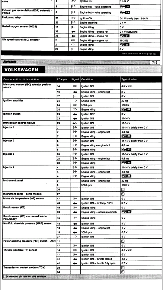
I searched for data on this vehicle and i found autodata info on the mp9 ecu.
The data states, key on engine off i should get 4v on the map output wire.
I did test the harness as i mentioned but everything seems to be ok hence i asked if there is any other method that i can use in testing the harness (im not so educated in electronics and wirng so u will have to give me an indepth expl lol)
The ecu is mounted placed in the raintray (under front wipers) ecu is aluminium and corroded quite bad im assuming water seeped in and probably shorted something out.
I am failing on this vehicle and i will try any tests suggested
Sent from my SM-G531H using Tapatalk
Please Log in or Create an account to join the conversation.
- Ash03
-
Topic Author
- Offline
- Premium Member
-
- Posts: 147
- Thank you received: 6
Postive lead on battery+ and negative lead on the 5v ref or signal wire to check for a short to ground?
Is it necessary for a short to ground on a 5v ref to measure 0volts? In other words, can a power wire thats shorted to ground show a voltage close the required voltage?
Sent from my SM-G531H using Tapatalk
Please Log in or Create an account to join the conversation.
- Ash03
-
Topic Author
- Offline
- Premium Member
-
- Posts: 147
- Thank you received: 6
Sent from my SM-G531H using Tapatalk
Please Log in or Create an account to join the conversation.
- Ash03
-
Topic Author
- Offline
- Premium Member
-
- Posts: 147
- Thank you received: 6
Sent from my SM-G531H using Tapatalk
Please Log in or Create an account to join the conversation.
- Ash03
-
Topic Author
- Offline
- Premium Member
-
- Posts: 147
- Thank you received: 6
1. Is there any way to test the ecu by myself? I have very basic tools though (dvom and a 12v test light)
2. What does it mean when the ecu says SHORT TO POSITIVE? Is the signal wire or reference wire being shorted or the short can be either of them and has to be tested?
3. How is the knock sensor tested? This car has a 3pin knock sensor and i noticed there is no 5v ref on any of its wires.
Im not sure if the 5v ref is shared between the sensors as each sensor has its own 5v ref wire. It could be shared inside the ecu.
If it is shared inside the ecu, is it possible for the ecu to be throwing a map code but the problem really lies with the tps or distributor?
Sent from my SM-G531H using Tapatalk
Please Log in or Create an account to join the conversation.
- Ben
-
- Offline
- Platinum Member
-

- Posts: 1098
- Thank you received: 215
Please Log in or Create an account to join the conversation.
- Ash03
-
Topic Author
- Offline
- Premium Member
-
- Posts: 147
- Thank you received: 6
The car has one water temp sensor which is a 4 pin sensor. which I believe 2 pins are for the temp gauge in cluster and 2 pins are for the ecu.
It has a throttle cable. And i did do the throttle adaptation anyways, and quite a few times too.
I did view live data on the vehicle after all the testing sorry for not mentioning it.
Via live data (measuring blocks) i get the following values:
Water temp - Liva data water temp matches with cluster temperature and seems to be somewhat the correct water temp.
Air intake temp - when engine is at operating temp, air temp reads +- 50degrees (Celsius)
Throttle position - with map sensor unplugged at idle the throttle position varies from 5-7 degrees(car does not idle with map plugged in neither can i hold the rev any close to idle. if not on WOT the car wants to cut out)
Map - varies from 400-900 mbar with the sensor plugged in (higher rpm = higher mbar)
i will run vcds again and repost the logs just to be 100% sure
Please Log in or Create an account to join the conversation.
- Ben
-
- Offline
- Platinum Member
-
- Posts: 1098
- Thank you received: 215
Please Log in or Create an account to join the conversation.
- Ash03
-
Topic Author
- Offline
- Premium Member
-
- Posts: 147
- Thank you received: 6
This car does not have an egr system or lambda sensor, as I mentioned its a very basic system yet confusing
Please Log in or Create an account to join the conversation.
- Ben
-
- Offline
- Platinum Member
-
- Posts: 1098
- Thank you received: 215
Please Log in or Create an account to join the conversation.
- Ash03
-
Topic Author
- Offline
- Premium Member
-
- Posts: 147
- Thank you received: 6
Throttle opens smoothly on measuring blocks - max limit 87degrees
Voltage also increases smoothly when using a dvom - max limit around 4.5v
With all sensors plugged in, and fault codes cleared from previous unplugged sensors, no codes reappear.
This vehicle does not have an iac solenoid, its has an idle control stepper motor built into the tps, which is built into the throttle body.
The throttlebody has an 8 pin plug
Pin 1: idle control motor +12v
Pin 2: idle control motor ground
Pin 3: closed throttle position switch for idle motor
Pin 4: tps +5v supply/reference
Pin 5: tps signal to ecu
Pin 6: not used
Pin 7: ground (not identified on wiring diagram, but confirmed via the tests i have done)
Pin 8: closed throttle position switch for idle motor
I assume that pin 3 and pin 8 are for minimum and maximum positions, as in min=closed and max=wot
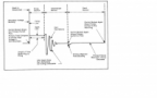
This is not an original wiring diagram from vw (tried to get one but i couldn't), its a diagram that i have found on google after tons of searching and seems to be the most accurate.
So do i disconnect pin 5 and then try?
Please Log in or Create an account to join the conversation.
- Ben
-
- Offline
- Platinum Member
-
- Posts: 1098
- Thank you received: 215
Please Log in or Create an account to join the conversation.